Mounting the Sensor
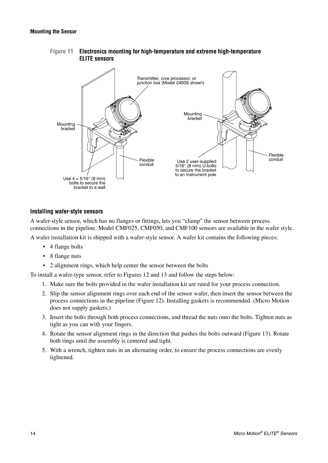
Figure 11 Electronics mounting for high-temperature and extreme high-temperature ELITE sensors
Transmitter, core processor, or junction box (Model 2400S shown)
Mounting ![]()
bracket
Mounting ![]()
bracket
Flexible | Use 2 |
conduit | 5/16″ (8 mm) |
| to secure the bracket |
Use 4 × 5/16″ (8 mm) | to an instrument pole |
| |
bolts to secure the |
|
bracket to a wall |
|
![]() Flexible conduit
Flexible conduit
Installing wafer-style sensors
A
A wafer installation kit is shipped with a
•4 flange bolts
•8 flange nuts
•2 alignment rings, which help center the sensor between the bolts
To install a
1.Make sure the bolts provided in the wafer installation kit are rated for your process connection.
2.Slip the sensor alignment rings over each end of the sensor wafer, then insert the sensor between the process connections in the pipeline (Figure 12). Installing gaskets is recommended. (Micro Motion does not supply gaskets.)
3.Insert the bolts through both process connections, and thread the nuts onto the bolts. Tighten nuts as tight as you can with your fingers.
4.Rotate the sensor alignment rings in the direction that pushes the bolts outward (Figure 13). Rotate both rings until the assembly is centered and tight.
5.With a wrench, tighten nuts in an alternating order, to ensure the process connections are evenly tightened.
14 | Micro Motion® ELITE® Sensors |