GLOSSARY OF SYMBOLS
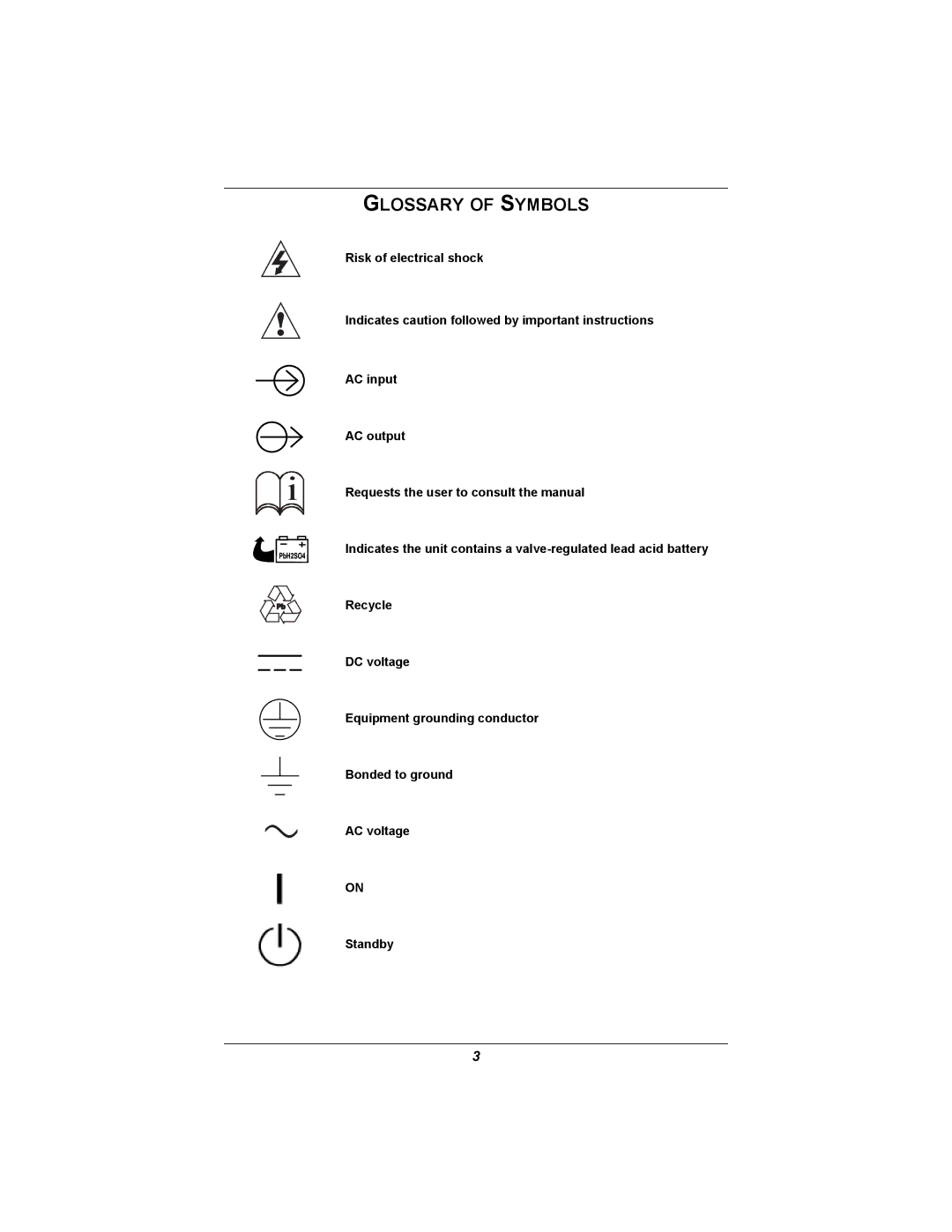
Risk of electrical shock
Indicates caution followed by important instructions
AC input
AC output
i | Requests the user to consult the manual |
|
Indicates the unit contains a
Recycle
DC voltage
Equipment grounding conductor
Bonded to ground
AC voltage
ON
Standby
3