GXT5000R-208 specifications
The Emerson GXT5000R-208 is a high-performance uninterruptible power supply (UPS) designed to deliver reliable power protection for critical systems in data centers, industrial applications, and other mission-critical environments. This UPS is engineered for efficiency, redundancy, and performance, making it a trusted choice among IT professionals and facility managers.One of the key features of the GXT5000R-208 is its double-conversion online technology. This technology ensures that the output power is consistent and free from fluctuations, providing pure sine wave output. This feature is particularly important for sensitive electronic equipment, as it maintains the integrity and operational stability of critical systems even in the event of input power disturbances such as surges, sags, or outages.
The GXT5000R-208 is capable of delivering a power capacity of 5000 VA / 5000 W with a nominal input voltage of 208-volt systems. Its advanced design allows for easy adaptability to various configurations, making it suitable for both single-phase and three-phase applications. The UPS is equipped with a wide input voltage range, which enhances its compatibility with different electrical infrastructures.
Another notable characteristic of the Emerson GXT5000R-208 is its modular design. The UPS can be easily expanded or reconfigured according to the changing needs of the facility, offering scalability for future growth. With hot-swappable batteries, users can perform maintenance or upgrades without downtime, ensuring continuous operation.
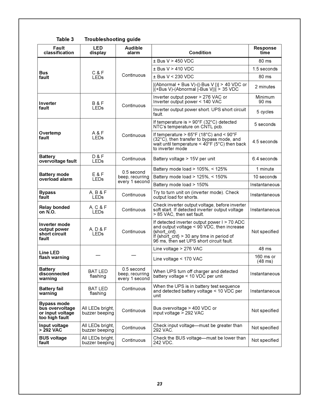
The GXT5000R-208 also incorporates powerful monitoring and management features. It comes with an intuitive LCD display that provides real-time information regarding the UPS status, battery health, and operational parameters. The UPS can also be integrated with various management software solutions, allowing for remote monitoring and control via SNMP, USB, or RS-232 connections.
Furthermore, the unit is built with a robust battery management system, ensuring optimal battery performance and longevity. Its intelligent charging system reduces the risk of battery overcharging, thus extending battery life and enhancing overall system reliability.
In summary, the Emerson GXT5000R-208 stands out for its reliable double-conversion online technology, scalability, and advanced monitoring capabilities. Its design prioritizes efficiency and adaptability, ensuring that organizations can maintain operational continuity and protect their critical systems against power disruptions. Whether in a data center or industrial setting, the GXT5000R-208 is a dependable UPS solution that meets the demanding requirements of modern power management.

