Selecting the Right Motor for the Right Drive
Control Techniques
1.Determine the application’s continuous and peak torque requirements at various motor shaft speeds, then refer to motor data tables and the
2.Once the motor family is selected, refer to the Control Techniques Servo Motors brochure to select a specific motor that delivers the required torque and speed. Make note of the continuous and peak current (Amps) requirements of the selected motor.
3.Check the ratings tables on page 19 of this brochure to select the drive model that delivers adequate continuous and peak current for the selected motor.
4.Go to the Control Techniques Servo Motors brochure to select motor power and feedback cables for the selected drive/motor combination.
Check that the rotor inertia of the selected motor has a ratio of <10 when calculated with the load inertia using the following equation:
Load inertia / rotor inertia
Note: A gear reducer will reduce the load inertia based on the following equation:
Reflected load inertia = load inertia / (gear ratio) 2
When specifying a motor system, be sure to consider such factors as
Electronic Nameplates
Some motors fitted with
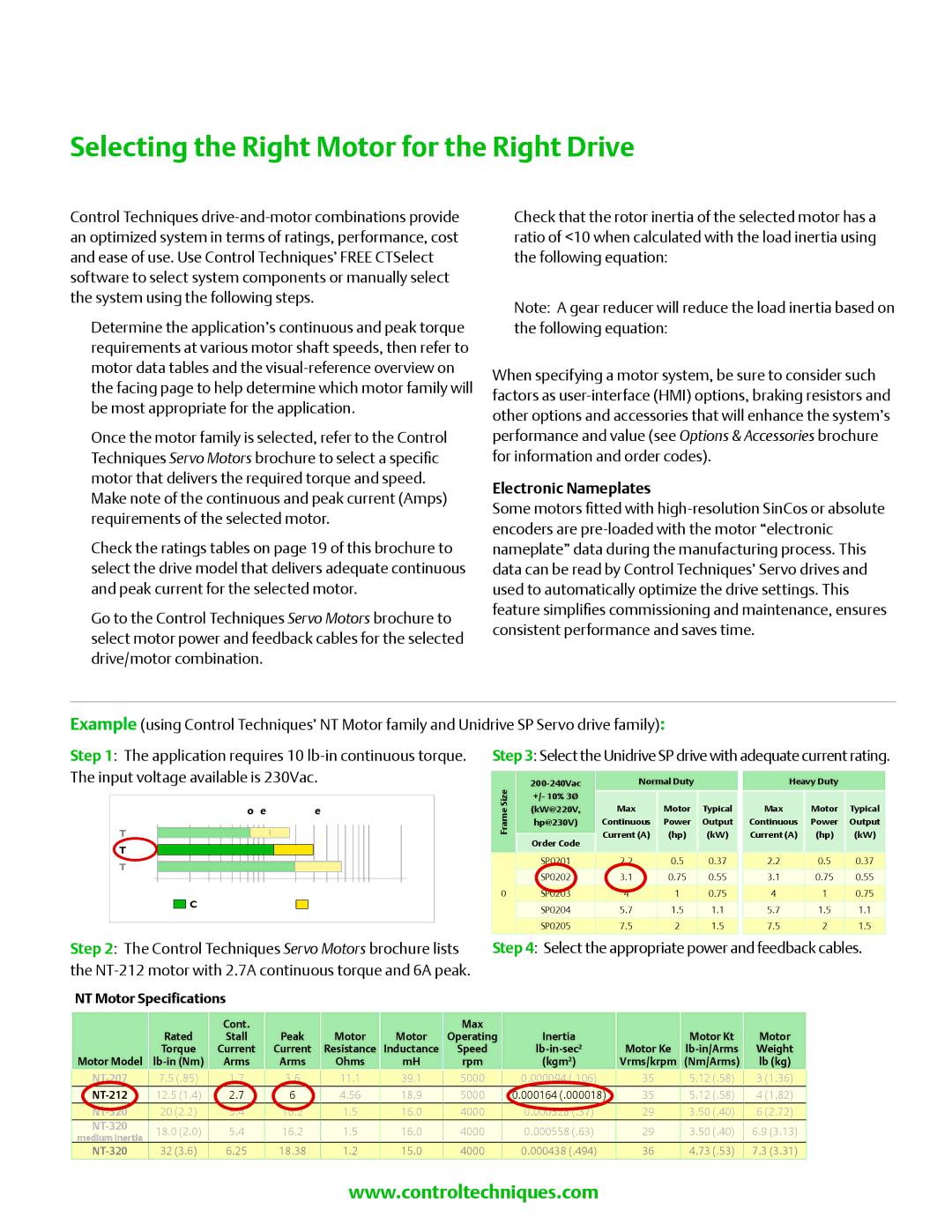
Example (using Control Techniques’ NT Motor family and Unidrive SP Servo drive family):
Step 1: The application requires 10
Step 3: Select the Unidrive SP drive with adequate current rating.
Frame |
| NT Torque Range | |
Size |
|
|
|
7.5 | 21288.5 |
| |
12.5 | 37.5 |
| |
20 |
| 596 | |
1 |
| 10 | 100 |
| Continuous Stall | Peak | |
SizeFrame
0
| Normal Duty |
|
|
| ||
+/- 10% 3Ø |
|
|
|
|
| |
| (kW@220V, | Max | Motor |
| Typical | |
| hp@230V) | Continuous | Power |
| Output | |
| Order Code | Current (A) | (hp) |
| (kW) | |
|
|
|
|
|
| |
| SP0201 |
| 0.5 |
| 0.37 |
|
| 2.2 |
|
| |||
|
|
|
|
|
|
|
| SP0202 | 3.1 | 0.75 |
| 0.55 |
|
|
|
|
|
|
|
|
| SP0203 | 4 | 1 |
| 0.75 |
|
|
|
|
|
|
|
|
| SP0204 | 5.7 | 1.5 |
| 1.1 |
|
|
|
|
|
|
|
|
| SP0205 | 7.5 | 2 |
| 1.5 |
|
|
|
|
|
|
|
|
Heavy Duty
Max | Motor | Typical |
Continuous | Power | Output |
Current (A) | (hp) | (kW) |
|
|
|
2.2 | 0.5 | 0.37 |
|
|
|
3.1 | 0.75 | 0.55 |
|
|
|
4 | 1 | 0.75 |
|
|
|
5.7 | 1.5 | 1.1 |
|
|
|
7.5 | 2 | 1.5 |
|
|
|
Step 2: The Control Techniques Servo Motors brochure lists | Step 4: Select the appropriate power and feedback cables. | |||||||||||||||||||||
the |
|
|
|
|
|
|
|
|
| |||||||||||||
| NT Motor Specifications |
|
|
|
|
|
|
|
|
|
|
|
|
|
|
|
|
| ||||
|
|
|
|
| Cont. |
|
|
|
|
|
|
| Max |
|
|
|
|
|
|
|
|
|
|
|
| Rated |
| Stall |
| Peak |
| Motor | Motor |
| Operating | Inertia |
|
|
| Motor Kt |
| Motor | |||
|
|
| Torque |
| Current |
| Current |
| Resistance Inductance |
| Speed |
|
| Motor Ke |
| Weight | ||||||
| Motor Model |
| Arms |
| Arms |
| Ohms | mH |
| rpm |
| (kgm2) |
| Vrms/krpm | (Nm/Arms) |
| lb (kg) | |||||
|
| 7.5 (.85) |
| 1.7 |
| 3.6 |
| 11.1 |
| 39.1 |
| 5000 |
| 0.000094 (.106) |
| 35 |
| 5.12 (.58) |
| 3 (1.36) |
| |
|
|
|
|
|
|
|
|
|
|
|
| |||||||||||
|
| 12.5 (1.4) |
| 2.7 |
| 6 |
| 4.56 |
| 18.9 |
| 5000 |
| 0.000164 (.000018) |
| 35 |
| 5.12 (.58) |
| 4 (1.82) |
| |
|
| 20 (2.2) |
| 5.4 |
| 16.2 |
| 1.5 |
| 16.0 |
| 4000 |
| 0.000328 (.37) |
| 29 |
| 3.50 (.40) |
| 6 (2.72) |
| |
|
| 18.0 (2.0) |
| 5.4 |
| 16.2 |
| 1.5 |
| 16.0 |
| 4000 |
| 0.000558 (.63) |
| 29 |
| 3.50 (.40) |
| 6.9 (3.13) |
| |
| medium inertia |
|
|
|
|
|
|
|
|
|
|
| ||||||||||
|
| information32 (3.6) 6.25on |
| Control18.38 |
| Techniques’1.2 |
| Servo15.0 motor4000offering,0.refer000438to(.494)brochure number36 |
| 4BRO.73 | 1107. | |||||||||||
www.controltechniques.com | 13 |
