Model NGA2000 TO2
Instruction Manual
Install replacement Sensor in reverse order. Check Sensor for leaks and add electrolyte as described in Section
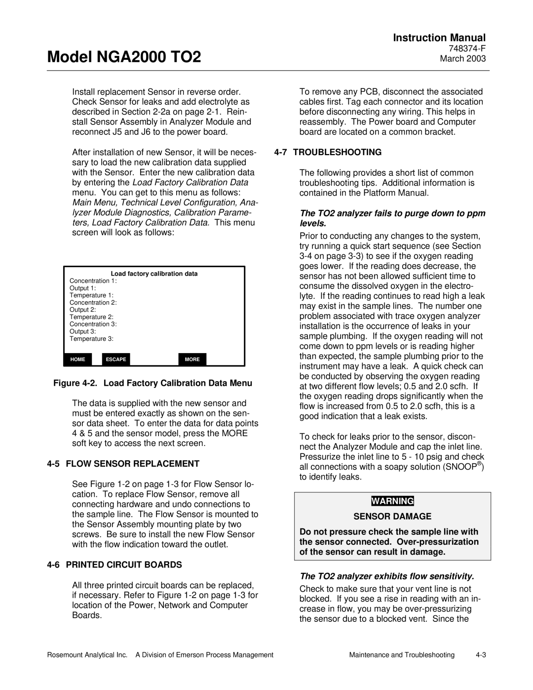
After installation of new Sensor, it will be neces- sary to load the new calibration data supplied with the Sensor. Enter the new calibration data by entering the Load Factory Calibration Data menu. You can get to this menu as follows: Main Menu, Technical Level Configuration, Ana- lyzer Module Diagnostics, Calibration Parame- ters, Load Factory Calibration Data. This menu screen will look as follows:
Load factory calibration data
Concentration 1:
Output 1:
Temperature 1:
Concentration 2:
Output 2:
Temperature 2:
Concentration 3:
Output 3:
Temperature 3:
HOME |
| ESCAPE |
| MORE |
|
|
|
|
|
Figure 4-2. Load Factory Calibration Data Menu
The data is supplied with the new sensor and must be entered exactly as shown on the sen- sor data sheet. To enter the data for data points 4 & 5 and the sensor model, press the MORE soft key to access the next screen.
4-5 FLOW SENSOR REPLACEMENT
See Figure
4-6 PRINTED CIRCUIT BOARDS
All three printed circuit boards can be replaced, if necessary. Refer to Figure
To remove any PCB, disconnect the associated cables first. Tag each connector and its location before disconnecting any wiring. This helps in reassembly. The Power board and Computer board are located on a common bracket.
4-7 TROUBLESHOOTING
The following provides a short list of common troubleshooting tips. Additional information is contained in the Platform Manual.
The TO2 analyzer fails to purge down to ppm levels.
Prior to conducting any changes to the system, try running a quick start sequence (see Section
To check for leaks prior to the sensor, discon- nect the Analyzer Module and cap the inlet line. Pressurize the inlet line to 5 - 10 psig and check all connections with a soapy solution (SNOOP®) to identify leaks.
WARNING
SENSOR DAMAGE
Do not pressure check the sample line with the sensor connected.
The TO2 analyzer exhibits flow sensitivity.
Check to make sure that your vent line is not blocked. If you see a rise in reading with an in- crease in flow, you may be
Rosemount Analytical Inc. A Division of Emerson Process Management | Maintenance and Troubleshooting |