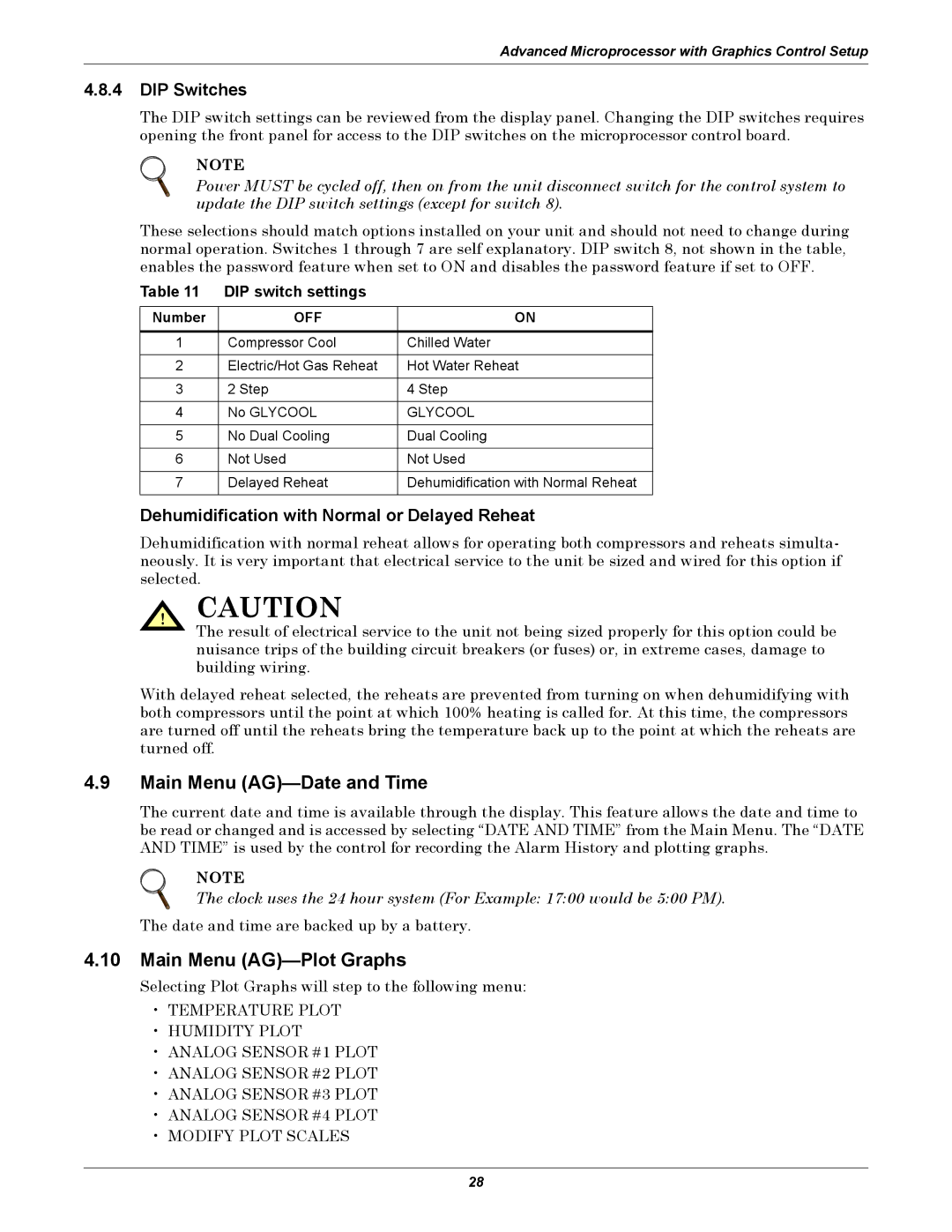
VE, DH, VH, DE specifications
Emerson is a well-known brand in the field of automation solutions, offering a range of products that cater to various industries. Among its diverse portfolio, Emerson’s products like DE (Digital Electronics), VH (Variable Frequency Drives), DH (Distributed Control Systems), and VE (Valve Positioners) stand out for their advanced features, cutting-edge technologies, and unique characteristics.Digital Electronics (DE) from Emerson represents the backbone of modern automation systems. These devices are characterized by their highly reliable digital communication capabilities, providing robust solutions for process monitoring and control. DE products integrate seamlessly with various automation platforms, allowing for easy data exchange and system interoperability. The advanced analytics embedded in these systems enable predictive maintenance strategies, enhancing overall operational efficiency.
Variable Frequency Drives (VH) are integral to motor control technologies, maximizing energy efficiency in various applications. Emerson's VH drives are designed for flexibility, supporting multiple motor types and configurations. These drives utilize pulse width modulation (PWM) technology, allowing for precise speed control and improved application performance. Their built-in protection features help extend motor life, prevent downtime, and reduce maintenance costs. Furthermore, the user-friendly interfaces of VH drives facilitate quick setup and troubleshooting.
Distributed Control Systems (DH) from Emerson provide a holistic approach to managing complex industrial processes. They enable centralized control while ensuring that local operations continue seamlessly. DH systems are characterized by their modular architecture, making them highly scalable and adaptable to changing operational needs. Advanced control algorithms within these systems help optimize processes, ensuring maximum productivity. Additionally, their enhanced cybersecurity features protect critical industrial operations from potential threats.
Emerson's Valve Positioners (VE) play a crucial role in regulating flow and pressure in various processes. These devices provide precise positioning capabilities, enhancing the performance of control valves. The VE systems incorporate smart technologies such as adaptive control and diagnostics, allowing them to self-tune and deliver accurate performance over time. Their compact design and robust build ensure they operate effectively in challenging environments.
In summary, Emerson's DE, VH, DH, and VE offerings embody the latest innovations in automation technology. Their main features, including digital communication, energy efficiency, scalability, and precision control, cater to the diverse demands of modern industries. With these products, Emerson not only enhances operational efficiency but also paves the way for intelligent automation solutions that are crucial for the future of industrial processes.

