SET-UP INSTRUCTIONS
1.Remove packing material from top of box.
2.Lift chimney section out and set aside.
3.Remove remaining items and packing from inside outdoor gas fireplace firebox.
4.Lift firebox out of box and sit on flat surface near desired final location. Leave adequate room around outdoor gas fireplace to work. Locking ring for chimney should be facing down.
Figure 5
5.Remove washers and nuts from three legs. Install the three legs using the bolts, washers and nuts provided. Reach through the opening in the outdoor gas fireplace to tighten the leg bolts securely.
Figure 5
6.Invert the outdoor gas fireplace firebox to sit on its legs.
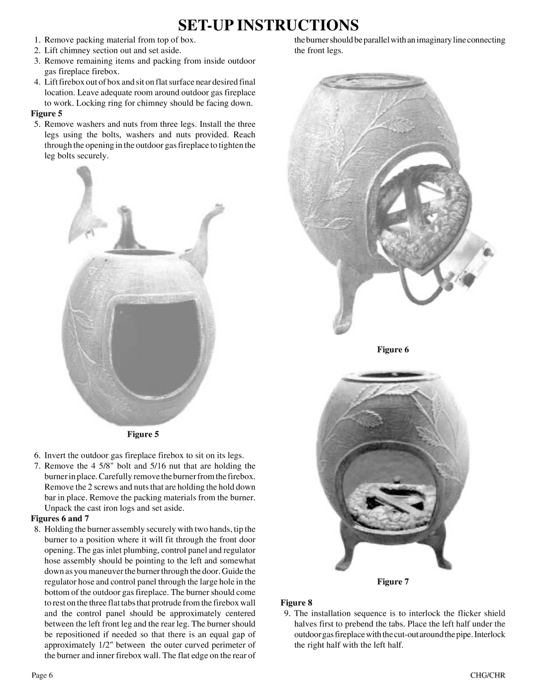
7.Remove the 4 5/8" bolt and 5/16 nut that are holding the burner in place. Carefully remove the burner from the firebox. Remove the 2 screws and nuts that are holding the hold down bar in place. Remove the packing materials from the burner. Unpack the cast iron logs and set aside.
Figures 6 and 7
8.Holding the burner assembly securely with two hands, tip the burner to a position where it will fit through the front door opening. The gas inlet plumbing, control panel and regulator hose assembly should be pointing to the left and somewhat down as you maneuver the burner through the door. Guide the regulator hose and control panel through the large hole in the bottom of the outdoor gas fireplace. The burner should come to rest on the three flat tabs that protrude from the firebox wall and the control panel should be approximately centered between the left front leg and the rear leg. The burner should be repositioned if needed so that there is an equal gap of approximately 1/2" between the outer curved perimeter of the burner and inner firebox wall. The flat edge on the rear of
the burner should be parallel with an imaginary line connecting the front legs.
Figure 6
Figure 7
Figure 8
9.The installation sequence is to interlock the flicker shield halves first to prebend the tabs. Place the left half under the outdoor gas fireplace with the
Page 6 | CHG/CHR |