CIBV-30-20 specifications
Empire Comfort Systems CIBV-30-20 is a versatile and efficient heating solution designed to meet the needs of both residential and commercial spaces. This direct vent gas fireplace boasts an array of features that make it a popular choice for those looking to enhance their indoor environment with warmth and style.One of the main features of the CIBV-30-20 is its sleek and contemporary design. The fireplace comes with a clean-faced front that allows for a seamless integration into any decor. Its compact size, with a 30-inch width, makes it suitable for various settings, from cozy living rooms to larger commercial spaces. The large viewing area maximizes the sight of the flames, providing an inviting ambiance and a warm atmosphere.
Performance is a key characteristic of the CIBV-30-20. It operates using natural gas or propane, allowing users to choose the fuel type that best fits their needs. With an impressive heat output of up to 25,000 BTUs, this fireplace efficiently heats the room, ensuring comfort during the cold months. Empire Comfort Systems has engineered the fireplace to deliver consistent and reliable performance, making it an ideal choice for year-round use.
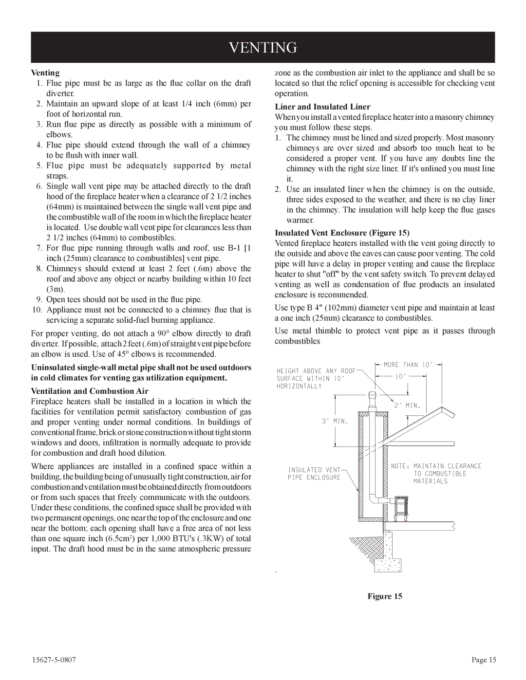
Another significant technology integrated into the CIBV-30-20 is its direct vent system. This feature allows for safe and efficient venting, as it draws air from the outside to fuel the fire, thus eliminating the risk of indoor air pollution. The balanced flue technology ensures that combustion gases are vented outside, maintaining good air quality indoors.
In terms of controls, the CIBV-30-20 is equipped with a reliable millivolt system, which allows for easy operation without the need for electricity. For added convenience, optional remote control kits are available, enabling users to adjust flame height and heat levels from a distance.
The Empire Comfort Systems CIBV-30-20 also prioritizes efficiency. With an efficiency rating of up to 75%, it provides substantial warmth while minimizing energy consumption, making it an eco-friendly heating option.
In summary, the Empire Comfort Systems CIBV-30-20 combines modern aesthetics with advanced heating technology. Its features, including direct vent capability, high heat output, and efficient performance, make it a standout solution for anyone seeking a reliable and stylish heating appliance. Whether for home or business use, the CIBV-30-20 is designed to deliver warmth, comfort, and a welcoming ambiance.

