ASSEMBLY OF STOVE CASTING (continued)

12.The following procedure will provide a snug fit between the casting front and the casting sides. Grasp the right, front leg, push inward on the leg in order to provide a snug fit between the casting front and the casting side. Continue to hold the right, front leg as you completely tighten the (2) 3/8" bolts that attach the leg pad to the right, casting side. Repeat procedure for left, front leg to achieve a snug fit between the casting front and the casting side.

13.Remove the casting front from the casting.

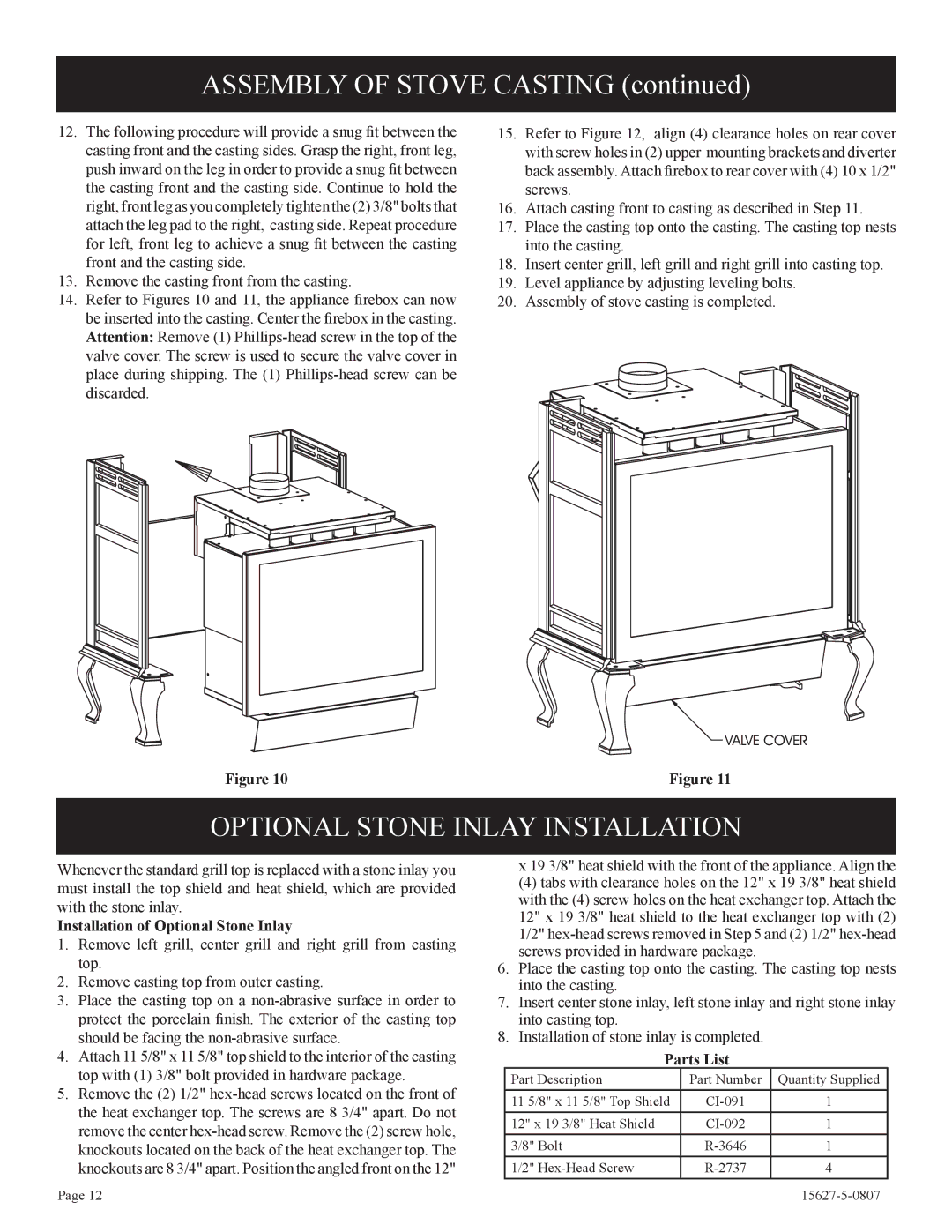
14.Refer to Figures 10 and 11, the appliance firebox can now be inserted into the casting. Center the firebox in the casting. Attention: Remove (1) Phillips-head screw in the top of the valve cover. The screw is used to secure the valve cover in place during shipping. The (1) Phillips-head screw can be discarded.

15. Refer to Figure 12, align (4) clearance holes on rear cover with screw holes in (2) upper mounting brackets and diverter back assembly. Attach firebox to rear cover with (4) 10 x 1/2" screws.

16. Attach casting front to casting as described in Step 11.

17. Place the casting top onto the casting. The casting top nests into the casting.

18. Insert center grill, left grill and right grill into casting top.

19.Level appliance by adjusting leveling bolts.

20.Assembly of stove casting is completed.

Figure 10

Figure 11

OPTIONAL STONE INLAY INSTALLATION

Whenever the standard grill top is replaced with a stone inlay you must install the top shield and heat shield, which are provided with the stone inlay.

Installation of Optional Stone Inlay

1.Remove left grill, center grill and right grill from casting top.

2.Remove casting top from outer casting.

3.Place the casting top on a non-abrasive surface in order to protect the porcelain finish. The exterior of the casting top should be facing the non-abrasive surface.

4.Attach 11 5/8" x 11 5/8" top shield to the interior of the casting top with (1) 3/8" bolt provided in hardware package.

5.Remove the (2) 1/2" hex-head screws located on the front of the heat exchanger top. The screws are 8 3/4" apart. Do not remove the center hex-head screw. Remove the (2) screw hole, knockouts located on the back of the heat exchanger top. The knockouts are 8 3/4" apart. Position the angled front on the 12"

x 19 3/8" heat shield with the front of the appliance. Align the

(4) tabs with clearance holes on the 12" x 19 3/8" heat shield with the (4) screw holes on the heat exchanger top. Attach the 12" x 19 3/8" heat shield to the heat exchanger top with (2) 1/2" hex-head screws removed in Step 5 and (2) 1/2" hex-head screws provided in hardware package.

6.Place the casting top onto the casting. The casting top nests into the casting.

7.Insert center stone inlay, left stone inlay and right stone inlay into casting top.

8.Installation of stone inlay is completed.

Parts List

Part Description

Part Number

Quantity Supplied

11 5/8" x 11 5/8" Top Shield

CI-091

1

12" x 19 3/8" Heat Shield

CI-092

1

3/8" Bolt

R-3646

1

1/2" Hex-Head Screw

R-2737

4

Page 12

15627-5-0807

Page 12
Image 12
Empire Comfort Systems CIBV-30-20 Optional Stone Inlay Installation, Installation of Optional Stone Inlay, Parts List

CIBV-30-20 specifications

Empire Comfort Systems CIBV-30-20 is a versatile and efficient heating solution designed to meet the needs of both residential and commercial spaces. This direct vent gas fireplace boasts an array of features that make it a popular choice for those looking to enhance their indoor environment with warmth and style.

One of the main features of the CIBV-30-20 is its sleek and contemporary design. The fireplace comes with a clean-faced front that allows for a seamless integration into any decor. Its compact size, with a 30-inch width, makes it suitable for various settings, from cozy living rooms to larger commercial spaces. The large viewing area maximizes the sight of the flames, providing an inviting ambiance and a warm atmosphere.

Performance is a key characteristic of the CIBV-30-20. It operates using natural gas or propane, allowing users to choose the fuel type that best fits their needs. With an impressive heat output of up to 25,000 BTUs, this fireplace efficiently heats the room, ensuring comfort during the cold months. Empire Comfort Systems has engineered the fireplace to deliver consistent and reliable performance, making it an ideal choice for year-round use.

Another significant technology integrated into the CIBV-30-20 is its direct vent system. This feature allows for safe and efficient venting, as it draws air from the outside to fuel the fire, thus eliminating the risk of indoor air pollution. The balanced flue technology ensures that combustion gases are vented outside, maintaining good air quality indoors.

In terms of controls, the CIBV-30-20 is equipped with a reliable millivolt system, which allows for easy operation without the need for electricity. For added convenience, optional remote control kits are available, enabling users to adjust flame height and heat levels from a distance.

The Empire Comfort Systems CIBV-30-20 also prioritizes efficiency. With an efficiency rating of up to 75%, it provides substantial warmth while minimizing energy consumption, making it an eco-friendly heating option.

In summary, the Empire Comfort Systems CIBV-30-20 combines modern aesthetics with advanced heating technology. Its features, including direct vent capability, high heat output, and efficient performance, make it a standout solution for anyone seeking a reliable and stylish heating appliance. Whether for home or business use, the CIBV-30-20 is designed to deliver warmth, comfort, and a welcoming ambiance.