GAS SUPPLY

Consult the current National Fuel Gas Code, ANSI Z223.1 CAN/ CGA-B149 (.1 or .2) installation code.

Recommended Gas Pipe Diameter

Pipe Length

Schedule 40 Pipe

Tubing, Type L


Inside Diameter

Outside Diameter


Nat.

L.P.

Nat.

L.P.

0-10 feet

1/2”

3/8”

1/2”

3/8”

0-3 meters

12.7mm

9.5mm

12.7mm

9.5mm

10-40 feet

1/2”

1/2”

5/8”

1/2”

4-12 meters

12.7mm

12.7mm

15.9mm

12.7mm

40-100 feet

1/2”

1/2”

3/4”

1/2”

13-30 meters

12.7mm

12.7mm

19mm

12.7mm

100-150 feet

3/4”

1/2”

7/8”

3/4”

31-46 meters

19mm

12.7mm

22.2mm

19mm

Note: Never use plastic pipe. Check to confirm whether your local codes allow copper tubing or galvanized.

Note: Since some municipalities have additional local codes, it is always best to consult your local authority and installation code.

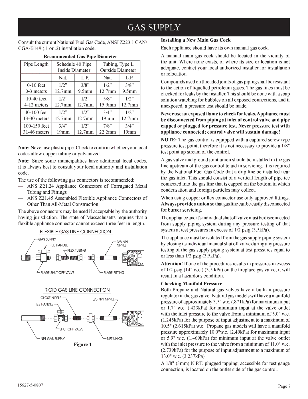
The use of the following gas connectors is recommended:

ANS Z21.24 Appliance Connectors of Corrugated Metal Tubing and Fittings

ANS Z21.45 Assembled Flexible Appliance Connectors of Other Than All-Metal Construction

The above connectors may be used if acceptable by the authority having jurisdiction. The state of Massachusetts requires that a flexible appliance connector cannot exceed three feet in length.

Figure 1

Installing a New Main Gas Cock

Each appliance should have its own manual gas cock.

A manual main gas cock should be located in the vicinity of the unit. Where none exists, or where its size or location is not adequate, contact your local authorized installer for installation or relocation.

Compounds used on threaded joints of gas piping shall be resistant to the action of liquefied petroleum gases. The gas lines must be checked for leaks by the installer. This should be done with a soap solution watching for bubbles on all exposed connections, and if unexposed, a pressure test should be made.

Never use an exposed flame to check for leaks.Appliance must be disconnected from piping at inlet of control valve and pipe capped or plugged for pressure test. Never pressure test with appliance connected; control valve will sustain damage!

NOTE: The gas control is equipped with a captured screw type pressure test point, therefore it is not necessary to provide a 1/8" test point up stream of the control.

A gas valve and ground joint union should be installed in the gas line upstream of the gas control to aid in servicing. It is required by the National Fuel Gas Code that a drip line be installed near the gas inlet. This should consist of a vertical length of pipe tee connected into the gas line that is capped on the bottom in which condensation and foreign particles may collect.

When using copper or flex connector use only approved fittings. Always provide a union so that gas line can be easily disconnected for burner servicing.

The appliance and it's individual shut off valve must be disconnected from supply piping system during any pressure testing of that system at test pressures in excess of 1/2 psig (3.5kPa).

The appliance must be isolated from the gas supply piping system by closing its individual manual shut off valve during any pressure testing of the gas supply piping system at test pressures equal to or less than 1/2 psig (3.5kPa).

Attention! If one of the procedures results in pressures in excess of 1/2 psig (14" w.c.) (3.5 kPa) on the fireplace gas valve, it will result in a hazardous condition.

Checking Manifold Pressure

Both Propane and Natural gas valves have a built-in pressure regulator in the gas valve. Natural gas models will have a manifold pressure of approximately 3.5" w.c. (.871kPa) for maximum input or 1.7" w.c. (.423kPa) for minimum input at the valve outlet with the inlet pressure to the valve from a minimum of 5.0" w.c. (1.245kPa) for the purpose of input adjustment to a maximum of 10.5" (2.615kPa) w.c. Propane gas models will have a manifold pressure approximately 10.0"w.c. (2.49kPa) for maximum input or 5.9" w.c. (1.469kPa) for minimum input at the valve outlet with the inlet pressure to the valve from a minimum of 11.0" w.c. (2.739kPa) for the purpose of input adjustment to a maximum of 13.0" w.c. (3.237kPa).

A 1/8" (3mm) N.P.T. plugged tapping, accessible for test gauge connection, is located on the outlet side of the gas control.

15627-5-0807

Page 7

Page 7
Image 7
Empire Comfort Systems CIBV-30-20 GAS Supply, Recommended Gas Pipe Diameter, Installing a New Main Gas Cock

CIBV-30-20 specifications

Empire Comfort Systems CIBV-30-20 is a versatile and efficient heating solution designed to meet the needs of both residential and commercial spaces. This direct vent gas fireplace boasts an array of features that make it a popular choice for those looking to enhance their indoor environment with warmth and style.

One of the main features of the CIBV-30-20 is its sleek and contemporary design. The fireplace comes with a clean-faced front that allows for a seamless integration into any decor. Its compact size, with a 30-inch width, makes it suitable for various settings, from cozy living rooms to larger commercial spaces. The large viewing area maximizes the sight of the flames, providing an inviting ambiance and a warm atmosphere.

Performance is a key characteristic of the CIBV-30-20. It operates using natural gas or propane, allowing users to choose the fuel type that best fits their needs. With an impressive heat output of up to 25,000 BTUs, this fireplace efficiently heats the room, ensuring comfort during the cold months. Empire Comfort Systems has engineered the fireplace to deliver consistent and reliable performance, making it an ideal choice for year-round use.

Another significant technology integrated into the CIBV-30-20 is its direct vent system. This feature allows for safe and efficient venting, as it draws air from the outside to fuel the fire, thus eliminating the risk of indoor air pollution. The balanced flue technology ensures that combustion gases are vented outside, maintaining good air quality indoors.

In terms of controls, the CIBV-30-20 is equipped with a reliable millivolt system, which allows for easy operation without the need for electricity. For added convenience, optional remote control kits are available, enabling users to adjust flame height and heat levels from a distance.

The Empire Comfort Systems CIBV-30-20 also prioritizes efficiency. With an efficiency rating of up to 75%, it provides substantial warmth while minimizing energy consumption, making it an eco-friendly heating option.

In summary, the Empire Comfort Systems CIBV-30-20 combines modern aesthetics with advanced heating technology. Its features, including direct vent capability, high heat output, and efficient performance, make it a standout solution for anyone seeking a reliable and stylish heating appliance. Whether for home or business use, the CIBV-30-20 is designed to deliver warmth, comfort, and a welcoming ambiance.