| OPTIONAL CONTROLLERS |
|
|
| MODELS |
|
|
FRBTP | Battery Operated Remote w/ Programmable Thermostat |
FRBTC | Battery Operated Remote w/ Thermostat |
|
|
TRW | Battery Operated Wireless Remote Wall Thermostat |
TMV2 | Thermostat, 2 Stage |
See your Mantis dealer for correct controller type.
INSTRUCTIONS MUST BE LEFT WITH THE OWNER FOR FUTURE REFERENCE AFTER INSTALLATION Installation Instructions for FRBTP, FRBTC, and TRW
The Remote Control FRBTP, FRBTC and TRW are all battery operated devices, which require a small amount of low voltage wiring. Begin installation by unplugging the unit and removing the front louver panel.
Remove blue jumper wire from junction block and save for future use. Using wire provided in the Mantis Owner’s Manual Package, connect remote wires using below schematic.
Black or white wire can be inserted in either remote control receiver connection hole. There is no polarity at this connection.
REMOTE
CONTROL RECEIVER
BLUE
BLACK |
| JUMPER WIRE |
| (TO BE REMOVED) | |
WHITE |
| |
|
|
WHITE ![]()
JUNCTION | C W2 W1 R |
|
|
|
| |||||||||||
BLOCK |
|
|
|
| ||||||||||||
|
|
|
|
|
|
|
|
|
|
|
|
|
|
|
| |
|
|
|
|
|
|
|
|
|
|
|
|
|
|
|
| TO |
|
|
|
|
|
|
|
|
|
|
|
|
|
|
|
| |
|
|
|
|
|
|
|
|
| BLUE |
|
|
| TRANSFORMER | |||
|
|
|
|
|
|
|
|
|
|
|
| |||||
|
|
|
|
|
|
| RED |
|
|
| TO “T1” (FRONT BURNER) | |||||
|
|
|
|
|
|
|
|
| ||||||||
|
|
|
|
|
| BLACK |
|
|
|
| TO “T2” (REAR BURNER) | |||||
|
|
|
|
|
|
|
|
|
| |||||||
|
|
|
|
| WHITE |
|
|
|
|
|
|
| TO “T1” | |||
|
|
|
|
|
|
|
|
|
|
| ||||||
|
|
|
|
| BLUE |
|
|
|
| TO “T2” | ||||||
|
|
|
|
|
|
|
|
| ||||||||
| Figure 49 |
|
|
|
| |||||||||||
Replace front louver panel and plug unit into outlet. Turn both burner switches to the ON position. Burner switches must remain in the ON position for remote to function. Set remote from the instructions provided with the remote control.
Note: When the heater or the Remote Control will not be used for long periods the burner switches should be in the OFF position, also in summer the heater should be turned off at the power point.
Installation Instruction for TMV2 - Two Stage Thermostat Model:
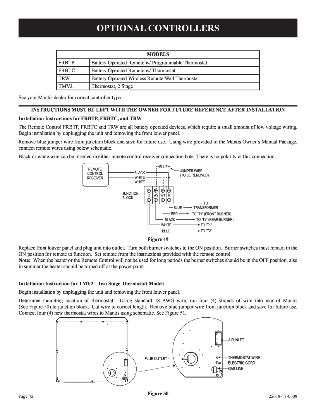
Begin installation by unplugging the unit and removing the front louver panel.
Determine mounting location of thermostat. Using standard 18 AWG wire, run four (4) strands of wire into rear of Mantis (See Figure 50) to junction block. Cut wire to correct length. Remove blue jumper wire from junction block and save for future use. Connect four (4) new thermostat wires to Mantis using schematic. See Figure 51.
Page 42 | Figure 50 | |
|