OPERATION INSTRUCTIONS/FLAME APPEARANCE
Flames from the pilot (rear right back side of the pan burner) as well as the main flame should be visually checked as the log set is installed.
In normal operation at full rate, the flame appearance should be sets of yellow flames above the rear burner section, and shorter blue flames with glowing embers on the front burner section.
NOTE: all flames will be random by design, flame height will go up and down.
Avoid any drafts that alter burner flame patterns. Do not allow fans to blow directly into fireplace. Do not place a blower inside the burner area of the firebox. Ceiling fans may create drafts that alter flame patterns. Sooting and improper burning will result.
During manufacturing, fabricating and shipping, various components of this appliance are treated with certain oils, films or bonding agents. These chemicals are not harmful, but may produce annoying smoke and smells as they are burned off during the initial operation of the appliance, possibly causing headaches or eye or lung irritation. This is a normal and temporary occurrence.
The initial
PILOT ASSEMBLY
![]() BURNER TUBE
BURNER TUBE
PIEZO IGNITOR
ON/OFF/REMOTE
VALVE PRESSURE TESTSWITCH PORT ACCESS HOLES
ON/OFF/PILOT
CONTROL KNOB
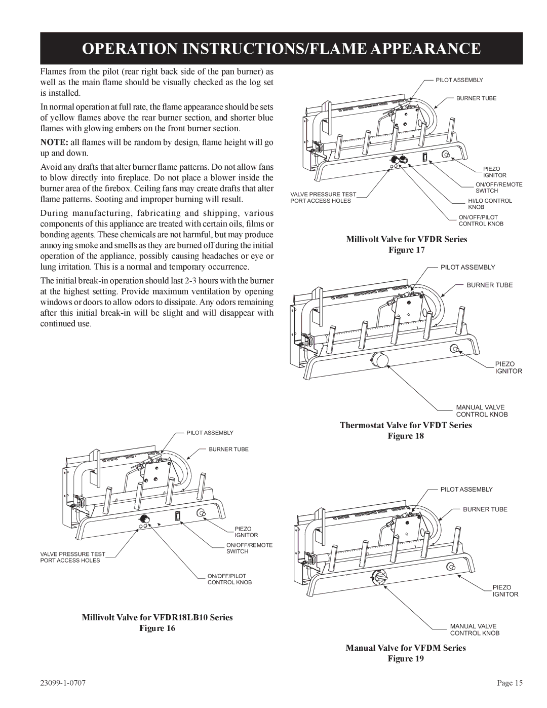
Millivolt Valve for VFDR18LB10 Series
Figure 16
PILOT ASSEMBLY
![]() BURNER TUBE
BURNER TUBE
| PIEZO |
| IGNITOR |
| ON/OFF/REMOTE |
VALVE PRESSURE TEST | SWITCH |
PORT ACCESS HOLES | HI/LO CONTROL |
| KNOB |
| ON/OFF/PILOT |
| CONTROL KNOB |
Millivolt Valve for VFDR Series
Figure 17
PILOT ASSEMBLY
BURNER TUBE
PIEZO
IGNITOR
MANUAL VALVE
CONTROL KNOB
Thermostat Valve for VFDT Series
Figure 18
PILOT ASSEMBLY
BURNER TUBE
PIEZO
IGNITOR
MANUAL VALVE
CONTROL KNOB
Manual Valve for VFDM Series
Figure 19
Page 15 |