8. MAINTENANCE
8.1CLEANING
Wipe the outside of the instrument with a soft, clean cloth.
Never use solvents or cleaning solutions of any type.
8.2CHANGING THE BATTERY PACK
To change the ATX612 battery pack:
• Hold the instrument with battery pack facing up.
• Using the maintenance tool provided with the instrument, turn
• Remove the battery pack. (See Section 8.2.1 for instructions of replacing the Nicad battery module)
•Place the battery pack on the instrument.
•Turn the hex screws clockwise until the screws are tight
and reach the stops. DO NOT OVER TIGHTEN.
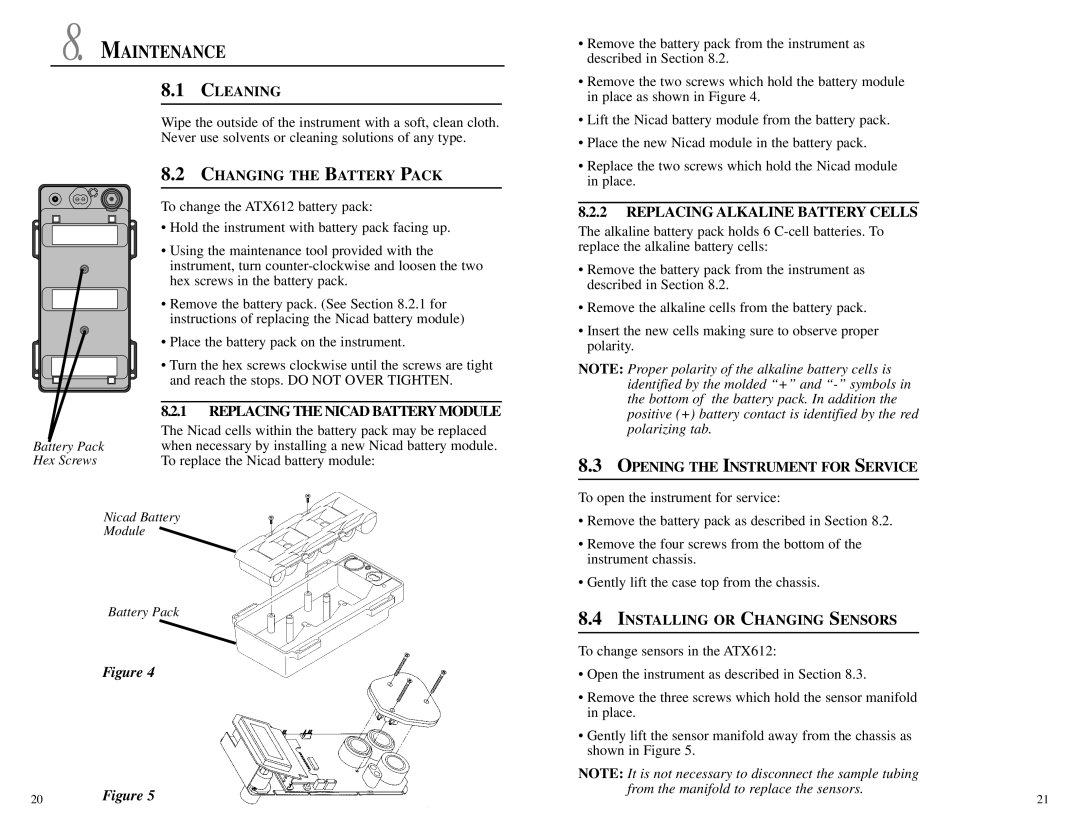
| 8.2.1 REPLACING THE NICAD BATTERY MODULE |
| The Nicad cells within the battery pack may be replaced |
Battery Pack | when necessary by installing a new Nicad battery module. |
Hex Screws | To replace the Nicad battery module: |
Nicad Battery
Module
Battery Pack
Figure 4
20Figure 5
•Remove the battery pack from the instrument as described in Section 8.2.
•Remove the two screws which hold the battery module in place as shown in Figure 4.
•Lift the Nicad battery module from the battery pack.
•Place the new Nicad module in the battery pack.
•Replace the two screws which hold the Nicad module in place.
8.2.2REPLACING ALKALINE BATTERY CELLS
The alkaline battery pack holds 6
•Remove the battery pack from the instrument as described in Section 8.2.
•Remove the alkaline cells from the battery pack.
•Insert the new cells making sure to observe proper polarity.
NOTE: Proper polarity of the alkaline battery cells is identified by the molded “+” and
8.3OPENING THE INSTRUMENT FOR SERVICE
To open the instrument for service:
•Remove the battery pack as described in Section 8.2.
•Remove the four screws from the bottom of the instrument chassis.
•Gently lift the case top from the chassis.
8.4INSTALLING OR CHANGING SENSORS
To change sensors in the ATX612:
•Open the instrument as described in Section 8.3.
•Remove the three screws which hold the sensor manifold in place.
•Gently lift the sensor manifold away from the chassis as shown in Figure 5.
NOTE: It is not necessary to disconnect the sample tubing from the manifold to replace the sensors.
21