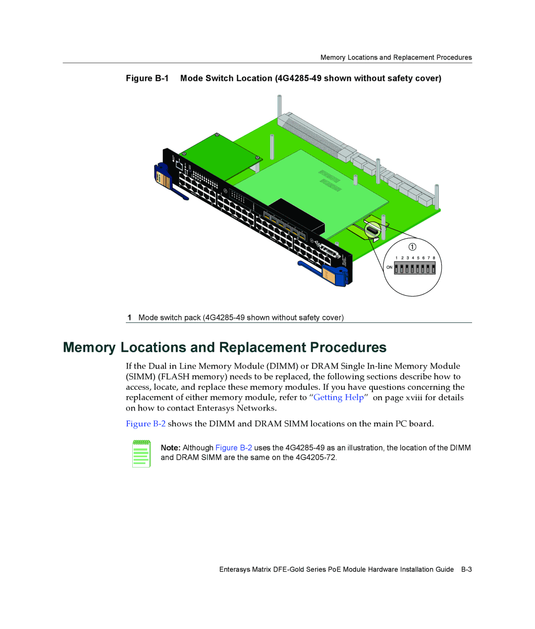
4G4205-72, 4G4285-49 specifications
Enterasys Networks is a distinguished name in the realm of networking solutions, offering a variety of high-performance switches and routers designed for enterprise environments. Among their impressive lineup, the 4G4285-49 and 4G4205-72 models stand out for their advanced capabilities and robust features that cater to the demanding needs of modern IT infrastructure.The Enterasys 4G4285-49 is a high-density Layer 3 switch that provides exceptional performance and reliability. It is equipped to handle the increasing data traffic common in enterprise networks, facilitating enhanced throughput and reduced latency. This model features 48 Gigabit Ethernet ports, ideal for connecting a vast array of devices within a network, along with one or two 10 Gigabit SFP+ uplink ports, ensuring fast data transmission to other network segments.
On the other hand, the 4G4205-72 is specifically designed as a versatile access switch with 24 Gigabit Ethernet ports and an additional 4 SFP+ uplink ports. This configuration makes it perfect for connecting endpoints like computers, printers, and other network devices while also providing scalability for future expansion.
Both models leverage advanced technologies such as Virtual LAN (VLAN) support, which helps in segmenting network traffic for better performance and security. Quality of Service (QoS) features are integrated, allowing administrators to prioritize critical applications and ensure optimal performance during high traffic periods. Additionally, security protocols like Access Control Lists (ACLs) and port security measures safeguard the network against unauthorized access.
The Enterasys 4G4285-49 and 4G4205-72 also support advanced management capabilities. With intuitive web-based interfaces and support for SNMP (Simple Network Management Protocol), IT teams can efficiently monitor network performance and troubleshoot issues as they arise.
In terms of build quality, both models are designed for reliability, featuring robust chassis and components that withstand the rigors of a data center environment. Their energy-efficient designs also contribute to reduced operational costs, aligning with the growing demand for sustainable networking solutions.
In summary, Enterasys Networks' 4G4285-49 and 4G4205-72 models combine high performance, advanced networking technologies, and robust security features, making them ideal choices for enterprises looking to enhance their network infrastructure and manage increasing data demands effectively.

