700 specifications
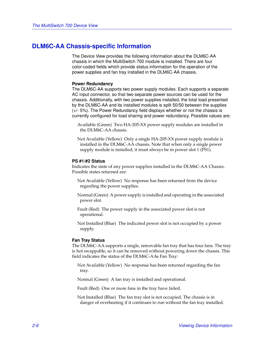
Enterasys Networks, a key player in the networking and security industry, offers an extensive range of solutions, among which is the Enterasys Networks 700 series. The Enterasys 700 series is designed to meet the demands of modern networking environments while providing a robust set of features, high performance, and scalability that appeals to organizations of various sizes.One of the main features of the Enterasys 700 series is its ability to deliver high-speed connectivity, which supports multiple Gigabit Ethernet ports. This ensures that organizations can efficiently handle bandwidth-intensive applications and a growing number of connected devices. The series is designed to facilitate seamless and reliable data transmission, making it suitable for environments that require consistent uptime and performance.
The Enterasys 700 series is built around advanced security protocols that are essential for protecting organizational data. These security features include integrated firewalls, intrusion detection systems, and comprehensive access control policies. This ensures that sensitive information remains secure from internal and external threats while providing IT administrators with the tools needed to manage security policies effectively.
Another notable characteristic of the Enterasys 700 series is its intelligent networking capabilities. The integration of advanced Quality of Service (QoS) mechanisms allows network administrators to prioritize critical applications, ensuring optimal performance for mission-critical services. This capability is especially important in environments that host multiple applications, as it empowers organizations to manage bandwidth efficiently and maintain service quality.
The Enterasys 700 series also incorporates advanced network management solutions, enabling centralized control and monitoring. This feature simplifies the administration of network resources, allowing IT teams to quickly diagnose issues and deploy solutions as needed. The user-friendly interface and comprehensive reporting tools further enhance the management experience, providing insights into network performance and health.
Furthermore, the Enterasys Networks 700 series is designed with scalability in mind. Organizations can easily expand their network infrastructure without the need for significant overhauls, accommodating future growth and technological advancements. This flexibility not only saves costs but also ensures that organizations remain competitive in an ever-evolving digital landscape.
In summary, the Enterasys Networks 700 series offers a rich suite of features and technologies that cater to modern networking needs. Its high-speed connectivity, robust security measures, intelligent networking capabilities, comprehensive management tools, and scalability make it an excellent choice for organizations looking to enhance their network infrastructure. Whether for small businesses or large enterprises, the Enterasys 700 series stands out as a reliable and versatile networking solution.
