Connecting Stacking Cables

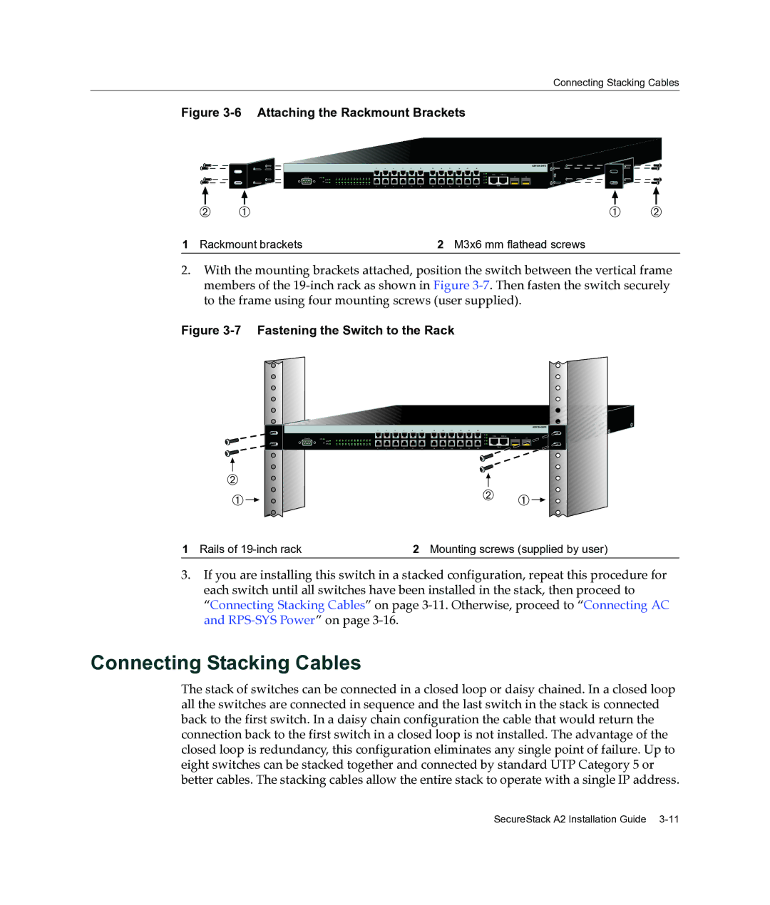
Figure 3-6 Attaching the Rackmount Brackets

1

3

5

7

9

11

13

15

17

19

21

23


25

25/Up

26/Down


Console

CPU

1

3

5

7

9

11

13

15

17

19

21

23


26


27

28


27


MGR


RPS

2

4

6

8

10

12

14

16

18

20

22

24


28


2

4

6

8

10

12

14

16

18

20

22

24


Stack


Á À

À

Á

1 Rackmount brackets

2 M3x6 mm flathead screws


2.With the mounting brackets attached, position the switch between the vertical frame members of the 19‐inch rack as shown in Figure 3‐7. Then fasten the switch securely to the frame using four mounting screws (user supplied).

Figure 3-7 Fastening the Switch to the Rack

1

3

5

7

9

11

13

15

17

19

21

23


25

25/Up

26/Down

Console

CPU

1

3

5

7

9

11

13

15

17

19

21

23


26


MGR


27


RPS

2

4

6

8

10

12

14

16

18

20

22

24


28


2

4


6


8


10


12


14

16


18


20


22


24


Stack


27

28

Á

Á


À

À

1 Rails of 19-inch rack

2 Mounting screws (supplied by user)

3.If you are installing this switch in a stacked configuration, repeat this procedure for each switch until all switches have been installed in the stack, then proceed to “Connecting Stacking Cables” on page 3‐11. Otherwise, proceed to “Connecting AC and RPS‐SYS Power” on page 3‐16.

Connecting Stacking Cables

The stack of switches can be connected in a closed loop or daisy chained. In a closed loop all the switches are connected in sequence and the last switch in the stack is connected back to the first switch. In a daisy chain configuration the cable that would return the connection back to the first switch in a closed loop is not installed. The advantage of the closed loop is redundancy, this configuration eliminates any single point of failure. Up to eight switches can be stacked together and connected by standard UTP Category 5 or better cables. The stacking cables allow the entire stack to operate with a single IP address.

SecureStack A2 Installation Guide 3-11

Page 39
Image 39
Enterasys Networks A2H124-24FX manual Connecting Stacking Cables, Attaching the Rackmount Brackets

A2H124-24FX specifications

Enterasys Networks A2H124-24FX is a high-performance network switch designed to meet the demands of modern data centers and enterprise environments. This switch exemplifies the blend of reliability, scalability, and advanced features that enterprises require to ensure seamless connectivity and data management.

One of the main features of the A2H124-24FX is its 24 Fast Ethernet (10/100) ports. These ports provide a robust foundation for connecting various devices within a network, making it ideal for workplaces that require extensive connectivity options. Additionally, the switch supports up to 4 Gigabit SFP (Small Form-factor Pluggable) uplink ports, which facilitate high-speed connections to backbone switches or routers, catering to bandwidth-intensive applications.

Another significant characteristic of the A2H124-24FX is its support for Power over Ethernet (PoE). This technology enables the switch to deliver power to connected devices such as IP phones, wireless access points, and security cameras through the same Ethernet cable that transmits data. This feature not only reduces the need for additional power supplies but also streamlines installation processes, reducing overall operational costs.

Security is a paramount concern for any enterprise network, and the A2H124-24FX addresses this through various advanced security features. It includes support for IEEE 802.1X Network Access Control, which ensures that only authenticated users can access the network. Additionally, it provides features such as MAC address filtering and VLAN support to segment network traffic and enhance overall security.

In terms of management, the Enterasys Networks A2H124-24FX is equipped with a user-friendly interface that allows network administrators to configure and monitor the switch effortlessly. It supports both CLI (Command Line Interface) and web-based management, providing flexibility depending on user preference.

This switch also supports advanced Layer 2 and Layer 3 capabilities, including Quality of Service (QoS) features that help prioritize traffic, ensuring that critical applications receive the necessary bandwidth for optimal performance.

In conclusion, the Enterasys Networks A2H124-24FX combines functionality, security, and ease of management, making it an ideal choice for businesses looking to enhance their network infrastructure. Its robust features and reliable performance can effectively support the complex demands of modern networking environments.