Installing the Switch on a Flat Surface
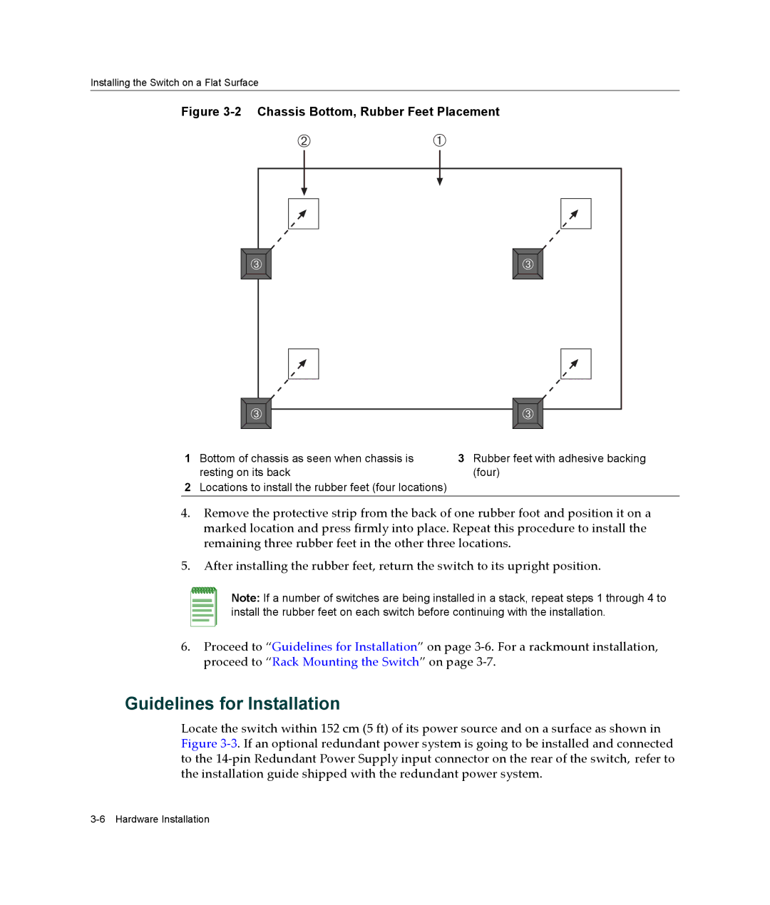
Figure 3-2 Chassis Bottom, Rubber Feet Placement
Á | À |
 |  |
 |  |
1Bottom of chassis as seen when chassis is resting on its back
2Locations to install the rubber feet (four locations)
3Rubber feet with adhesive backing (four)
4.Remove the protective strip from the back of one rubber foot and position it on a marked location and press firmly into place. Repeat this procedure to install the remaining three rubber feet in the other three locations.
5.After installing the rubber feet, return the switch to its upright position.
Note: If a number of switches are being installed in a stack, repeat steps 1 through 4 to install the rubber feet on each switch before continuing with the installation.
6.Proceed to “Guidelines for Installation” on page 3‐6. For a rackmount installation, proceed to “Rack Mounting the Switch” on page 3‐7.
Guidelines for Installation
Locate the switch within 152 cm (5 ft) of its power source and on a surface as shown in Figure 3‐3. If an optional redundant power system is going to be installed and connected to the 14‐pin Redundant Power Supply input connector on the rear of the switch, refer to the installation guide shipped with the redundant power system.