Front Panel Controls and Indicators
Front Panel Controls and Indicators
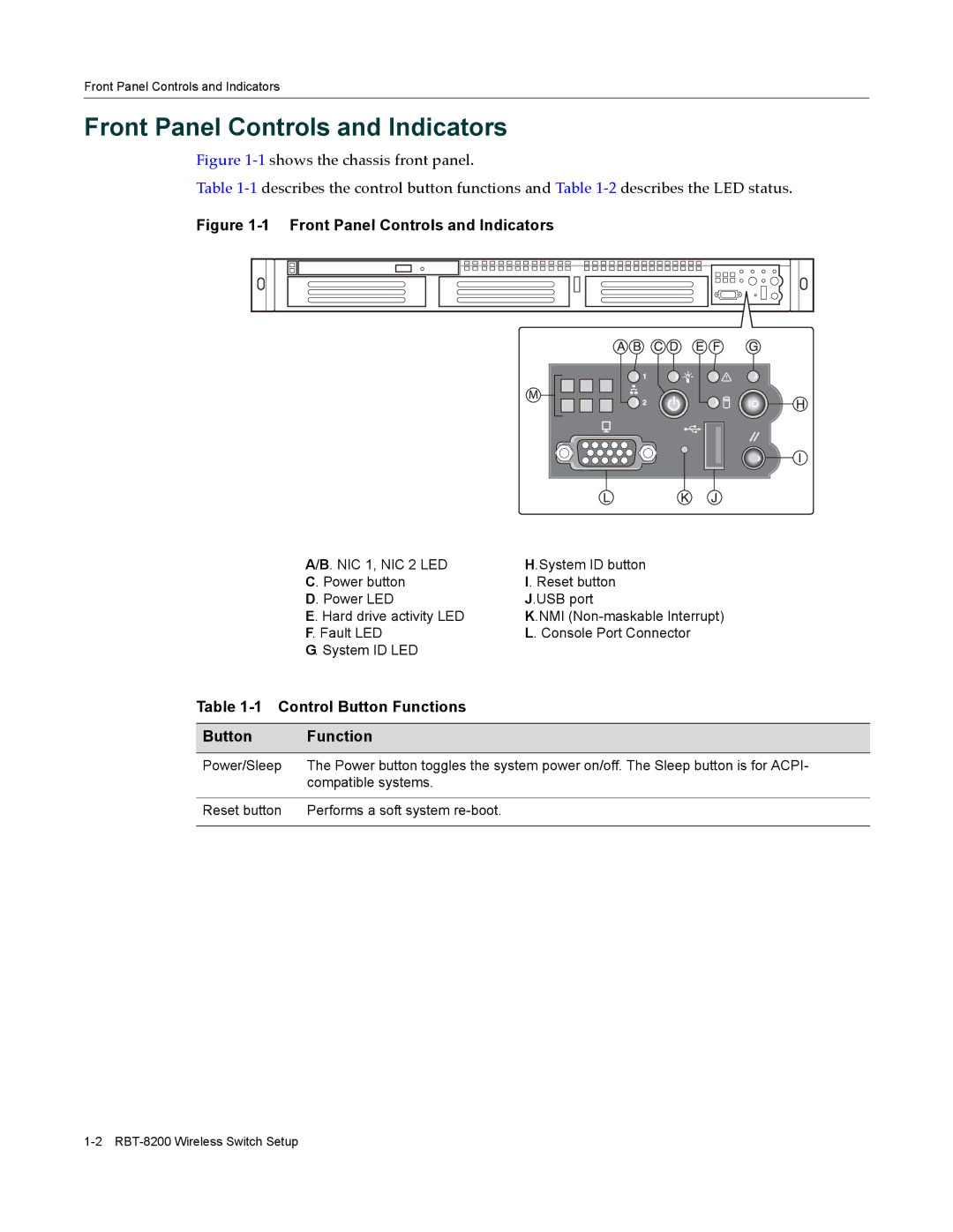
Figure 1‐1 shows the chassis front panel.
Table 1‐1 describes the control button functions and Table 1‐2 describes the LED status.
Figure 1-1 Front Panel Controls and Indicators
A/B. NIC 1, NIC 2 LED | H.System ID button |
C. Power button | I. Reset button |
D. Power LED | J.USB port |
E. Hard drive activity LED | K.NMI |
F. Fault LED | L. Console Port Connector |
G. System ID LED |
|
Table 1-1 Control Button Functions
Button Function
Power/Sleep | The Power button toggles the system power on/off. The Sleep button is for ACPI- |
| compatible systems. |
|
|
Reset button | Performs a soft system |
|
|
