3 Installing the Switch
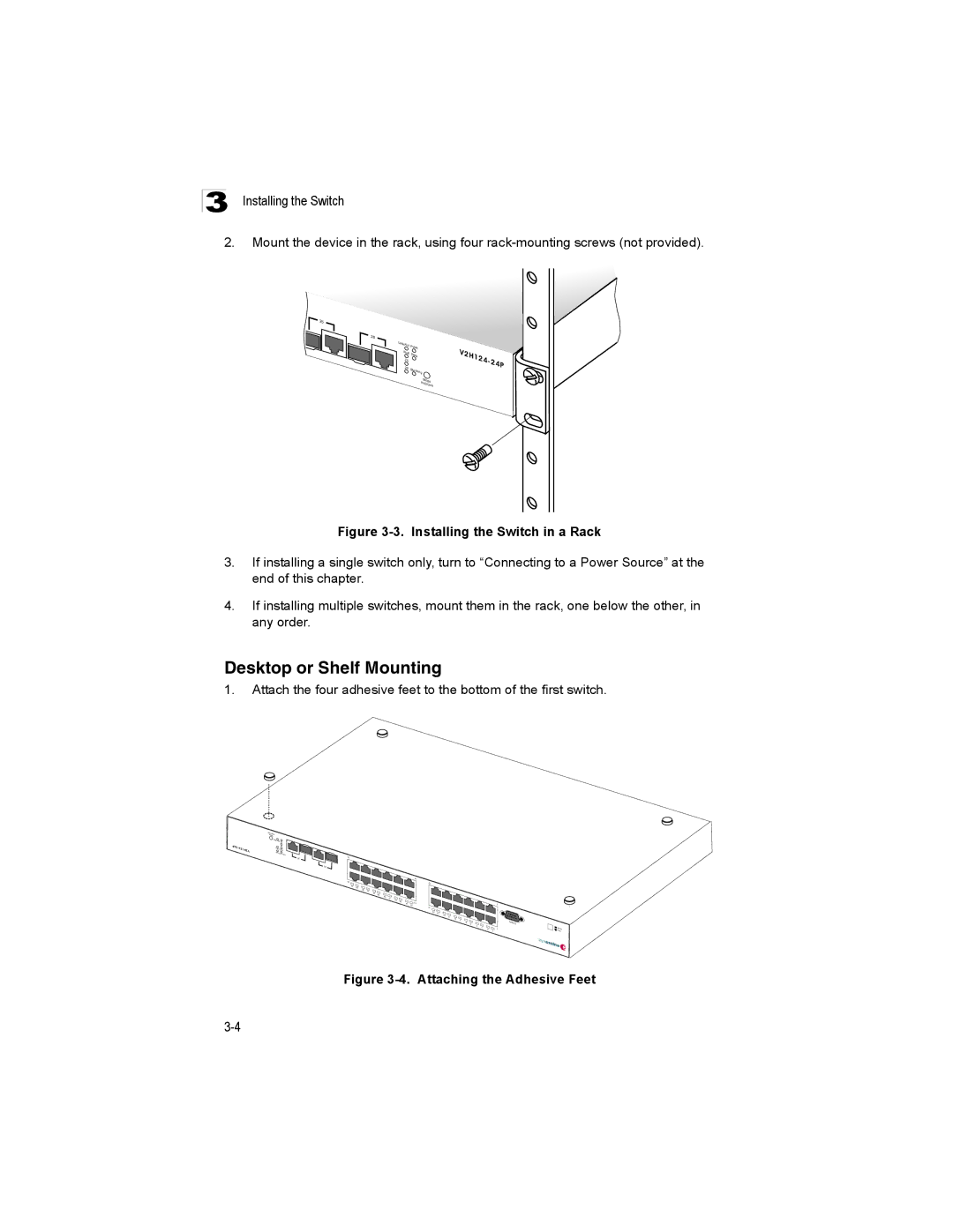
2.Mount the device in the rack, using four
25
26
Lin |
|
k/Act | PWR |
PoE | Diag |
| |
25 |
|
26 | Sta |
| cking |
Mode
PoE/Link
Figure 3-3. Installing the Switch in a Rack
3.If installing a single switch only, turn to “Connecting to a Power Source” at the end of this chapter.
4.If installing multiple switches, mount them in the rack, one below the other, in any order.
Desktop or Shelf Mounting
1.Attach the four adhesive feet to the bottom of the first switch.
k inL E/ o | P |
|
de o M |
| |
| ing ck | Sta 6 2 |
|
| |
|
| 5 2 |
| g | ia DE Po |
| RW P | |
|
| ct/A ink L |
6 2 | 4 2 |
| 5 2 |
|
|
|
|
|
|
| 4 1 |
|
|
|
|
|
|
|
3 | 2 |
|
|
|
|
| 2 1 |
|
|
|
|
|
|
|
|
|
|
|
|
|
|
|
|
|
|
|
| ||
| 24 | 23 |
|
|
|
|
|
|
|
|
|
|
|
|
|
| 2 | 21 |
|
|
|
|
|
|
|
|
|
|
|
|
|
| 20 | 91 |
|
|
|
|
|
|
|
|
|
|
|
|
|
| 18 | 17 |
|
|
|
|
|
|
|
|
|
|
|
|
|
| 16 | 15 |
|
|
|
|
|
|
|
|
|
|
|
|
|
| 3 1 |
|
|
|
|
|
|
| |
|
|
|
|
|
| 14 | 13 |
|
|
|
|
| 2 |
|
|
|
|
|
|
|
| 11 |
|
|
|
|
|
|
|
|
|
|
|
|
|
| 2 1 | 11 |
|
|
|
|
|
|
|
|
|
|
|
|
|
| 0 1 | 9 |
|
|
|
|
|
|
|
|
|
|
|
|
|
| 8 | 7 |
|
| el |
|
|
|
|
|
|
|
|
|
|
| 6 | 5 |
|
| o ns oC |
|
|
|
|
|
|
|
|
|
|
| 4 | 3 |
|
|
|
|
|
|
|
|
|
|
|
|
|
| 1 |
| |
|
|
|
|
|
|
|
|
|
|
|
| 2 | 1 |
|
![]() ert as M ve al S
ert as M ve al S