4 Making Network Connections
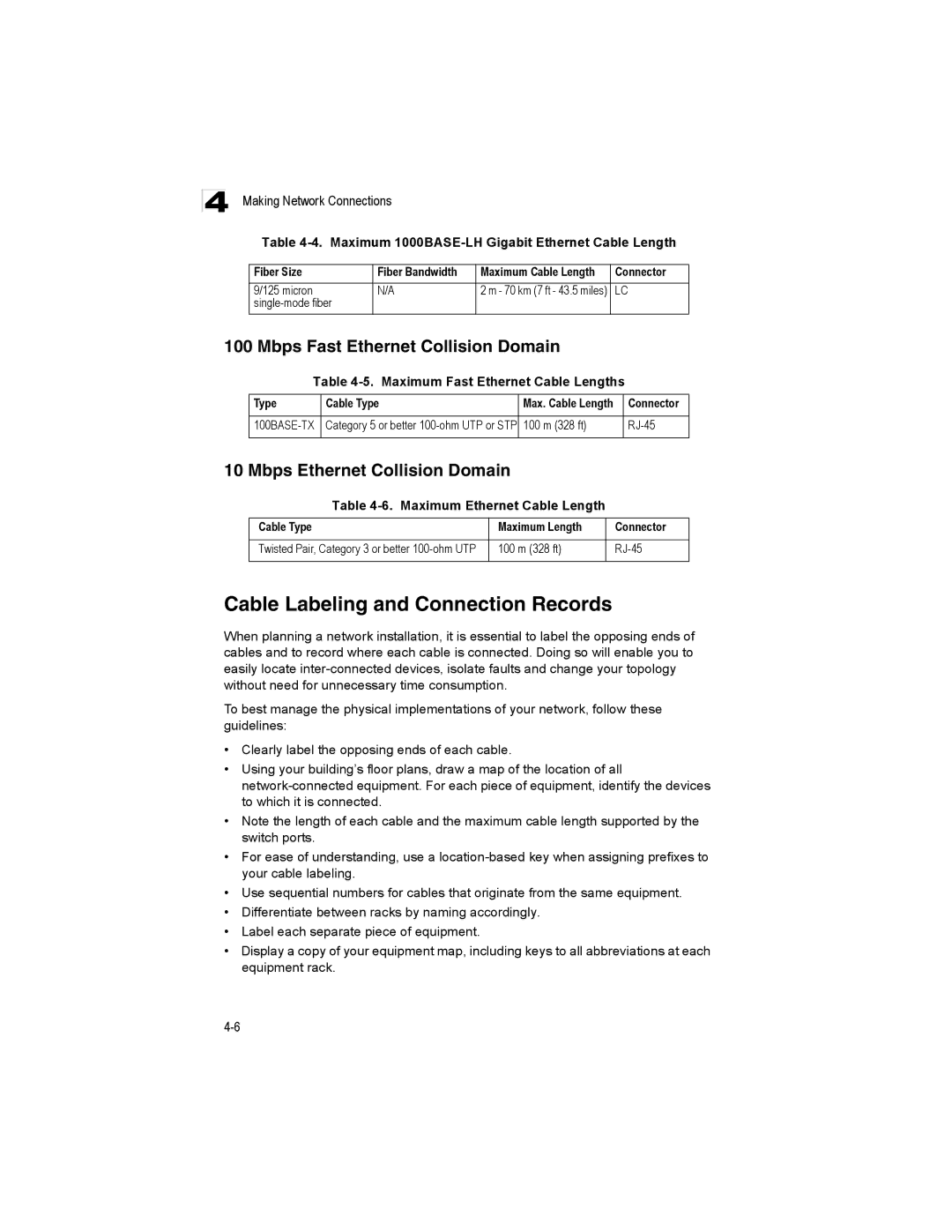
Table
Fiber Size | Fiber Bandwidth | Maximum Cable Length | Connector |
9/125 micron | N/A | 2 m - 70 km (7 ft - 43.5 miles) | LC |
|
|
|
100 Mbps Fast Ethernet Collision Domain
Table
Type | Cable Type | Max. Cable Length | Connector |
|
|
|
|
Category 5 or better | 100 m (328 ft) | ||
|
|
|
|
10 Mbps Ethernet Collision Domain
Table
Cable Type | Maximum Length | Connector |
|
|
|
Twisted Pair, Category 3 or better | 100 m (328 ft) | |
|
|
|
Cable Labeling and Connection Records
When planning a network installation, it is essential to label the opposing ends of cables and to record where each cable is connected. Doing so will enable you to easily locate
To best manage the physical implementations of your network, follow these guidelines:
•Clearly label the opposing ends of each cable.
•Using your building’s floor plans, draw a map of the location of all
•Note the length of each cable and the maximum cable length supported by the switch ports.
•For ease of understanding, use a
•Use sequential numbers for cables that originate from the same equipment.
•Differentiate between racks by naming accordingly.
•Label each separate piece of equipment.
•Display a copy of your equipment map, including keys to all abbreviations at each equipment rack.
