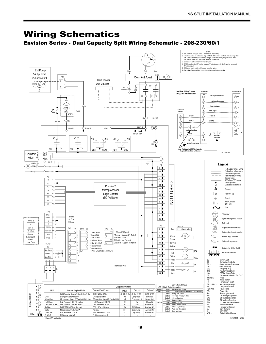
Envision Peripherals Series installation manual Wiring Schematics

Models: Series

1 36
Download 36 pages 34.9 Kb
Page 17
Image 17
Wiring Schematics

NS SPLIT INSTALLATION MANUAL

Wiring Schematics

Envision Series - Dual Capacity Split Wiring Schematic - 208-230/60/1


Notes:

S

1 - 24V Accessory relay (see SW2 - 3 for description of operation )

2 – This Switch allows the unit to down stage with the t -stat when OFF and finish on second stage when

C

ON. Finish second stage reduces stage changing in recip dual capacity compressors and should


be ON for unzoned Dual Cap E -Series or Premier 2 speed units.

R

3 - Comfort Alert fault output to Premier Control Board

4 – SW2-8 must be in the OFF position for pulsed “L” lockout signal and in the ON position for constant


“L” lockout signal.

Ext Pump


Blue

Red


Black

5 - DHW pump only in models with hot water generation option .


6 - Connection of remote unit that does not have a loop pump for slave operation .


1/2 hp Total


Comfort Alert

DC SOL

CS


208-230/60/1

PB1


+


2

Unit Power

-


2


208-230/60/1


Pump

Pump

1


CC


1

Run

Tan


G


Capacitor

(16)


Duel Fuel Wiring Diagram


Thermostat


Envision Split


G


Using Field Installed Relay

Y1


L2

L1


1st Stage Compressor


Y1


Blu


Y2

2nd Stage Compressor

Y2


DHW

Gry(9)


O

Reversing Valve


Pump


O


3A


Pink

Yel(8)


Fossil Fuel


L

Fault Signal

P1

Fuse


Furnace


LO


NOTE 5


C

Common

C

Common


C


Org(14)

Brn(15)


Blu(17)

Pink(13)


R

24 VAC

R

24 VAC


R


W


Fused L2

Fused L2

240V L2


240V L2

240V L1


Auxiliary Heat Relay


Shut


F1-10A 240V

G

Fan

G


P2


Auxiliary

Down


NO


NO

NO

NC

NO

NC


W

Heat Relay


F1-10A


Auxiliary Heat Relay


240V


CR1


COM

CR2


COM


CR3

COM


CR4

COM


Note: Field installed DPST dual fuel relay


R


(Required for dual fuel installation)


= chassis


Yel(6)


Comfort C


Blk(5)


Alert

Y2

Wht(4)


R


Y


Violet(3)

CCHI


C


Legend


P6


CC

Violet(2)

CC


8


Factory Low voltage wiring


Blk(1)


CC-GND


13


Factory Line voltage wiring


7


Field low voltage wiring


Field line voltage wiring


P1


4


Optional block


R


1


5

USED


DC Voltage PCB traces


C


2


Internal junction


Premier 2


14


Quick connect terminal


Y1


3


12


Y2


4


Microprocessor


Wire nut


6


W


5


Logic Control


Field wire lug


15

NOT


L1


LO


8


(DC Voltage)


N.O., N.C.


10


O


6


G


7


9


Relay Contacts-


2


Fuse


1


P2


3


Shut


11


T


Thermistor


ECM2


Down


1


G


Light emitting diode - Green


Air Flow


16


NOTE 6


C


2


Settings


Relay coil


C


C


3


P5


NOTE 3


SL1 In


SL1 In


4


Capacitor w/ bleed resistor


SW1


On

SW2

On


SW3

On


11

Tan

L

Comfort Alert


SL1 Out


SL1 Out


5


1


1

Test / Norm


1 2 Speed / 1 Speed

4


Switch - Condensate overflow

Optional


Not


6


2


2

Loop / Well


2 Normal / Finish on 2nd (Note 2)

9

Orange


RV


Switch - High pressure

Remote Unit


Used


7


3


3

Fan / Comp


3 No RPM / RPM


2

Orange


Without


4


4

Dehum / Norm


4 Electric Heat

/ Normal


Switch - Low pressure

Loop Pump


5


5

No Htg3 / Htg3


5 Envision / E Series or Premier

10

Not Used


NOTE 1


P3


6


6

Inputs / Norm


3

Not Used


Acc Com


1


7


7

Outputs / Norm


8

Pink


Switch -Hot Water On/Off


8


8

Pulse L / Constant L (NOTE 4)


T

HWL


1

Pink


2

3

1

Polarized connector


Acc NC


2


9


P


Acc NO


3


10


12

Yellow


T

WCL


11


5

Yellow


CA -


Comfort Alert


12


13

Blue


CC -


Compressor Contactor


LP

CO -


Condensate overflow sensor


Main Logic PCB

6

Blue


1

2

3


CR1 -


DHW pump relay


P4


CR2-


Loop pump relay


7

Black


HP

CR3 -


PSC Fan Speed Relay


14

Black


CR4 -


PSC Fan Power Relay


CS -


Compressor Solenoid **DC Coil**


F1 and F2 -


Fuses


HE -


Heater element


HP -


High pressure switch


R


Diagnostic Modes


Comfort Alert Status

ER1 to ER4 -

Aux heat stage relays


LED

Flash Code Description

LP -

Low pressure switch


R

LED

Normal Display Mode

Current Fault Status

Inputs

Outputs

Outputs2

Green

Solid

Module Has Power

PB1, PB2 -

Power blocks


Red

Solid

Y1 Present But Compressor Not Running

PS -

Power strip

PCB

R


Field Selection Dips - #1 On, #6 On, #7 On

#1 Off, #6 On, #7 On

#6 Off, #7 On

#6 On, #7 Off

#6 Off, #7 Off


Code 1

Long Run Time

RV -

Reversing Valve coil

R

Drain

Drain pan overflow Lockout

Drain pan overflow

Y1

Compressor Lo

Blower Lo


Code 2

System Pressure Trip

SW1 -

DIP package 12 position

LED


Code 3

Short Cycling

SW2 -

DIP package 8 position

R

Water Flow

FP thermistor (loop<15°F,well<30°F) Lockout

FP thermistor (loop<15°F, well<30°F)

Y2

Compressor Hi

Blower Med


Code 4

Locked Rotor

SW3 -

DIP package 5 position

Status

G

High Press

High Pressure > 600 PSI Lockout

High Pressure > 600 PSI

O

RV

Blower Hi

Yellow

Code 5

Open Circuit

SW4 -

Hot water pump enable switch

Low Press / Comp

Low Pressure < 40 PSI Lockout

Low Pressure < 40 PSI

G

FAN

Aux Heat #1


Code 6

Open Start Circuit

TS -

Thermal limit switch


Y


Air Flow

ECM2 RPM < 100 rpm Lockout

ECM2 RPM < 100 rpm

W

DHW Pump

Aux Heat #2


Code 7

Open Run Circuit

HWL -

Hot water limit sensor


R

Status

Microprocessor malfunction*

Not Used

SL1

Loop Pump 1

AuxHeat #3


Code 8

Welded Contactor

SC -

Start Contactor


Code 9

Low Voltage

SR -

Start Relay


DHW Limit

HWL thermistor > 130°F

HWL thermistor > 130°F

SL2

Loop Pump 2

Aux Heat #4


SW4


WCL -

Water Coil Limit Sensor


DHW off

DHW pump switch off

DHW pump switch off

--

--

--


*Green LED not flashing


97P774-31 3/9/07

15

Page 17
Image 17
Envision Peripherals Series installation manual Wiring Schematics