|
|
| Specifications | ||||
|
|
|
|
|
|
|
|
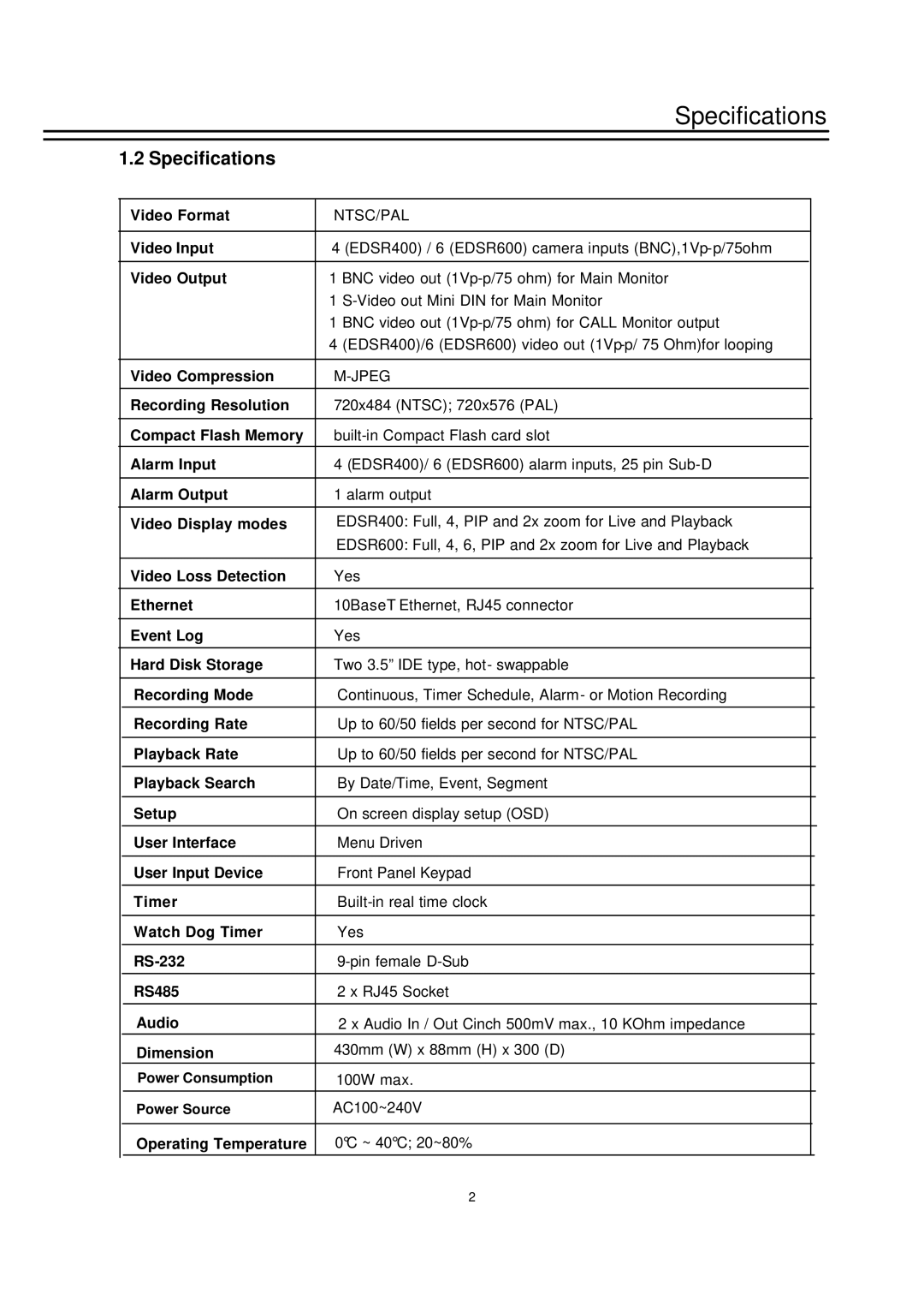
1.2 Specifications |
|
|
|
|
| ||
|
|
|
|
|
|
|
|
|
| Video Format | NTSC/PAL |
|
|
| |
|
|
|
|
|
|
| |
|
| Video Input | 4 (EDSR400) / 6 (EDSR600) camera inputs |
|
|
| |
|
|
|
|
|
|
|
|
|
| Video Output | 1 BNC video out |
|
|
| |
|
|
| 1 |
|
|
| |
|
|
| 1 BNC video out |
|
|
| |
|
|
| 4 (EDSR400)/6 (EDSR600) video out |
|
|
| |
|
|
|
|
|
|
| |
|
| Video Compression |
|
|
| ||
|
|
|
|
|
|
|
|
|
| Recording Resolution | 720x484 (NTSC); 720x576 (PAL) |
|
|
| |
|
|
|
|
|
|
| |
|
| Compact Flash Memory |
|
|
| ||
|
|
|
|
|
|
|
|
|
| Alarm Input | 4 (EDSR400)/ 6 (EDSR600) alarm inputs, 25 pin |
|
|
| |
|
|
|
|
|
|
|
|
|
| Alarm Output | 1 alarm output |
|
|
| |
|
|
|
|
|
|
| |
|
| Video Display modes | EDSR400: Full, 4, PIP and 2x zoom for Live and Playback |
|
|
| |
|
|
| EDSR600: Full, 4, 6, PIP and 2x zoom for Live and Playback |
|
|
| |
|
|
|
|
|
|
| |
|
| Video Loss Detection | Yes |
|
|
| |
|
|
|
|
|
|
| |
|
| Ethernet | 10BaseT Ethernet, RJ45 connector |
|
|
| |
|
|
|
|
|
|
| |
|
| Event Log | Yes |
|
|
| |
|
|
|
|
|
|
| |
|
| Hard Disk Storage | Two 3.5” IDE type, hot- swappable |
|
|
| |
|
|
|
|
|
|
| |
|
| Recording Mode | Continuous, Timer Schedule, Alarm- or Motion Recording |
|
|
| |
|
|
|
|
|
|
| |
|
| Recording Rate | Up to 60/50 fields per second for NTSC/PAL |
|
|
| |
|
|
|
|
|
|
| |
|
| Playback Rate | Up to 60/50 fields per second for NTSC/PAL |
|
|
| |
|
|
|
|
|
|
| |
|
| Playback Search | By Date/Time, Event, Segment |
|
|
| |
|
|
|
|
|
|
| |
|
| Setup | On screen display setup (OSD) |
|
|
| |
|
|
|
|
|
|
| |
|
| User Interface | Menu Driven |
|
|
| |
|
|
|
|
|
|
| |
|
| User Input Device | Front Panel Keypad |
|
|
| |
|
|
|
|
|
|
| |
|
| Timer |
|
|
| ||
|
|
|
|
|
|
| |
|
| Watch Dog Timer | Yes |
|
|
| |
|
|
|
|
|
|
| |
|
|
|
|
| |||
|
|
|
|
|
|
| |
|
| RS485 | 2 x RJ45 Socket |
|
|
| |
|
|
|
|
|
|
| |
|
| Audio | 2 x Audio In / Out Cinch 500mV max., 10 KOhm impedance |
|
|
| |
|
| Dimension | 430mm (W) x 88mm (H) x 300 (D) |
|
|
| |
|
| Power Consumption | 100W max. |
|
|
| |
|
|
|
|
|
|
| |
|
| Power Source | AC100~240V |
|
|
| |
|
|
|
|
|
|
|
|
|
| Operating Temperature | 0 C ~ 40 C; 20~80% |
|
|
| |
|
|
|
|
|
|
|
|
2