6 Channel Duplex Digital Video Recorder
INSTRUCTION MANUAL
4 Channel Duplex Digital Video Recorder
V1.05 2004/3/25
Safety Precautions
Safety Precautions
The power cord is the main power disconnect for all units
Important Safeguards
Appendix-C Serial Interface Specifications … … ..… … … … … … … …
Table of Contents
Appendix-A LAN functional specification … … … ..… … … … … … … … …
Appendix-D Alarm I/O pin assignment
B. General Features
1.1 Main Features A. Special Features
? Adjustable Brightness, Contrast and Color for each channel
Product Overview
Recording Resolution
Specifications
1.2 Specifications
Alarm Input
ON/OFF
Back Panel Connections
2. Back Panel Connections
AC100~240V
9 ALARM I/O Refer pin assignment in Appendix-D, Page
Back Panel Connections
System Connection
3. System Connection
Before Installation
SHUTTLE Ring and JOG Dial
Front Panel Keypads
4. Front Panel Keypads
CHANEL KEYS
21 IR Remote Controller receiver
Front Panel Keypads
Hold this key longer than 2 seconds for displaying the event log list
3 Switch Power On
Operation
5. Operation
4 Press MENU key to enter SET UP MENU
MENU flow
6. MENU FLOW
ARCHIVE
MENU flow
BUZZER
CALL
6.1 CLOCK SETTING MENU
MENU
In CLOCK/LANGUAGE SETTING MENU , we define
6.2 TIMER SETTING MENU
MENU
6.3 SEQUENCE SETTING MENU
In the SEQUENCE SETTING MENU, we define for MAIN Monitor
MENU
Default setting is CH01~CH04 for EDSR400, CH01~CH06 for EDSR600
6.4 TITLE SETTING MENU
In TITLE SETTING MENU , we define
MENU
Default setting is OFF for all cameras
6.5 COVERT SETTING MENU
In COVERT SETTING MENU , we define
MENU
6.6 ALARM RECORD SETTING MENU
In ALARM RECORDING MENU, we define
MENU
2 OP Operation Default OFF
6.7 MOTION SETTING MENU
In the MOTION RECORD SETTING MENU, we define
3 SEN Sensitivity HIGH, MIDDLE or LOW adjustable. Default MIDDLE
PRESS ENTER TO SELECT NODE USE JOG TO TOGGLE ON/OFF
MENU
5 Press 1-4/6 TO MANUAL EDIT
PRESS MENU TO EXIT
3 PRE-ALARM RECORD with Alarm In and Motion
6.8 RECORD SETTING MENU
2 ALARM RECORD for Alarm In and Motion detection
MENU
Network setting… … … … … … … … … … … …
6.9 NETWORK SETTING MENU
In the NETWORK SETTING MENU, we define
Please reboot to effect network setting
NOTE Settings for remote keyboards KS -KBK and KS-KBJ
6.10 CONTROL SETTING MENU
In the CONTROL SETTING MENU, we define
MENU
RECORD-IN, ALARM-IN, MOTION-IN, DISK FULL, VIDEO LOSS AND TIMER
6.11 BUZZER SETTING MENU
In BUZZER SETTING MENU, we define the buzzer
MENU
1 PICTURE SIZE
6.12 ARCHIVE SETTING MENU
MENU
2 TIME STAMP
6.13 CALL MONITOR SETTING MENU
MENU
CH, DWELL, EVENT
6.14 DISK SETTING MENU
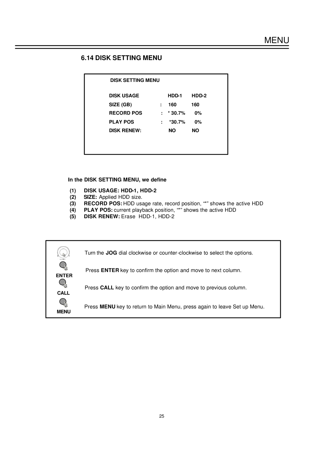
In the DISK SETTING MENU, we define 1 DISK USAGE HDD-1, HDD-2
MENU
MENU
6.15 SYSTEM SETTING MENU
In the SYSTEM SETTING MENU, we define
1 PLAY WITH AUDIO AUDIO-1, AUDIO-2
7.1 INSTANT RECORDING
7.2 ALARM RECORDING
Recording
2003/11/23 215647
1 Playback
Playing Back
8.1 NORMAL PLAYBACK
PLAY
1 Segment List search playback
Search Playback
8.2 SEARCH PLAYBACK
SEARCH
SEARCH
2 Alarm List search playback
Search Playback
ENTER
SEARCH
Search Playback
3 Date/Time Search Playback
SEARCH STOP
9.1 STILL IMAGE COPY
DATA EXPORT
9. DATA EXPORT
PAUSE COPY
PLAY
9.2 COPY TO MOVIE FILE
DATA EXPORT
COPY
DATA EXPORT
9.3 EXPORT EVENT LOG LIST
ALARM
Press „DISPLAY“ key and hold key for about 2 seconds DISPLAY
CALL monitor
MONITOR VIEWS / OPERATION
10. MONITOR VIEWS / OPERATION
10.1. MAIN MONITOR
10.2. CALL MONITORS
Press CALL to change settings for CALL monitor
MONITOR VIEWS / OPERATION
CALL
Installation example 2 remote operators, 1 EDSR600, 1 EDSR1600
11. REMOTE CONTROL
11.1 RS-485 REMOTE CONTROL
RJ45 RS485 pin assignment
Note EDSR400 Channel keys #1~4 EDSR600 Channel keys #1~6
IR Remote Controller
11.2 IR Remote Controller optional
#1~16 valid for EDSR900/1600 only
12. View From Internet/Intranet Basic Operations and Login Display
View From Internet/Intranet
Main Screen
View From Internet/Intranet
8. Control for Playback Video Speed 9. Control for Playback Position
Playback by SEGMENT LIST, click Refresh to show list
Playback by ALARM LIST, click Refresh to show list
View From Internet/Intranet
Playback by Date time
View From Internet/Intranet
12. Click to playback selected video segment
Specifications
LAN Functional Specification
Appendix-A
Used Ports
Time Lapse Mode Recording Time Table
? When Recording with 160GB HDD
Appendix-B
Estimated with typical image-low noise level
? When Recording with 320GB HDD
Appendix-B
Lower
The pin assignment of the D-SUB 9-pin connector
Appendix C Serial Interface Specifications
Serial Interface Specifications
2. Transmission setting
3. Remote Control Protocol
Appendix C Serial Interface Specifications
1-1. Sample control code packets
Length Byte Prefix 0x86, 0x87, or Receiver ID high byte
Appendix C Serial Interface Specifications
2-1. The format of message packet is as follows
Receiver ID low byte Opcode Byte Data Byte1 Data Byte2 Data Byte3
Appendix C Serial Interface Specifications
2-3. Receiver ID
2-4-1. OPcode
2-4. Opcode Byte & Data bytes
Appendix C Serial Interface Specifications
2-4-2. Remote keys OPcode=0x4B
D-SUB 25 pin female connector DVR
Alarm I/O pin assignment
Appendix-D
Figure 2 PR16D00400 Alarm extension board
P/N MSR4G0031B
EverFocus
EverFocus Electronics Corp
Head Office