23
19 | 21 | 22 |
|
20
25
18
17
16
15
14
13
10
12
11
10 | 9 | 8 | 6 | 5 |
|
| 7 |
|
24
1
2
3
4
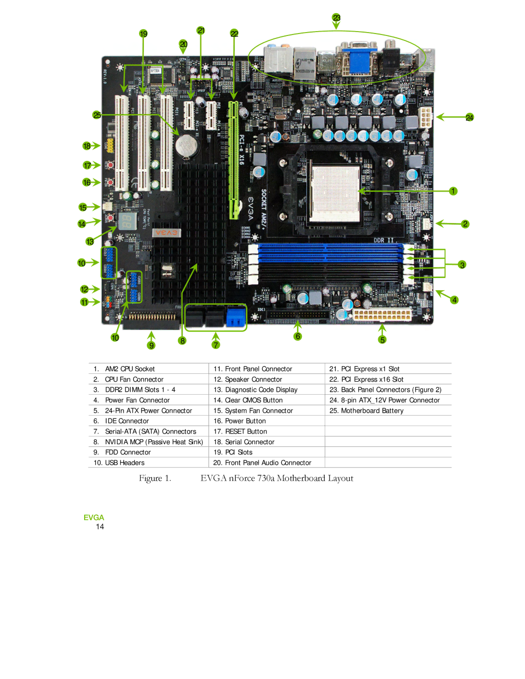
1. | AM2 CPU Socket | 11. | Front Panel Connector | 21. | PCI Express x1 Slot |
|
|
|
|
|
|
2. | CPU Fan Connector | 12. | Speaker Connector | 22. | PCI Express x16 Slot |
3. | DDR2 DIMM Slots 1 - 4 | 13. | Diagnostic Code Display | 23. | Back Panel Connectors (Figure 2) |
4. | Power Fan Connector | 14. | Clear CMOS Button | 24. | |
5. | 15. | System Fan Connector | 25. | Motherboard Battery | |
|
|
|
|
|
|
6. | IDE Connector | 16. | Power Button |
|
|
|
|
|
|
| |
7. | 17. RESET Button |
|
| ||
8. | NVIDIA MCP (Passive Heat Sink) | 18. | Serial Connector |
|
|
9. | FDD Connector | 19. | PCI Slots |
|
|
10. USB Headers | 20. Front Panel Audio Connector |
|
| ||
|
|
|
|
|
|
Figure 1. EVGA nForce 730a Motherboard Layout
EVGA 14