6.3 Unpacking
Carefully remove bolts and protective shipping hood. See Figure 3. Remove the bolts holding modules to shipping pallet. Also remove hardware bolting upper channels of modules together. Do not remove modules at this time. Base supports for horizontally stacked modules are more easily attached before removing modules from pallet (see Section 8 System Assembly).
Note: Placement of modules on shipping pallet has no relationship to final installation and should be disregarded.
UNPACKING MODULES
Figure 3
6.4 Handling of Modules
The design of the modular tray permits handling by a fork lift, portable crane or by a hoist sling . Whichever method is used, make sure equipment can safely handle the mod- ule weight. See Section 6.2 for module weights.
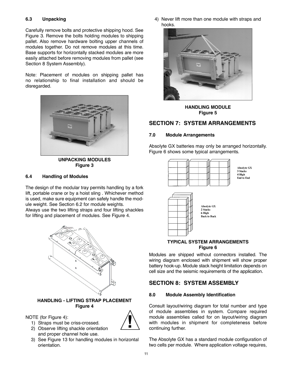
Always use the two lifting straps and four lifting shackles for lifting and placement of modules. See Figure 4.
4)Never lift more than one module with straps and hooks.
HANDLING MODULE
Figure 5
SECTION 7: SYSTEM ARRANGEMENTS
7.0 Module Arrangements
Absolyte GX batteries may only be arranged horizontally. Figure 6 shows some typical arrangements.
Absolyte GX 3 Stacks
4 High End to End
Absolyte GX
2 Stacks
6 High
Back to Back
HANDLING - LIFTINGFigureSTRAP4 PLACEMENT
NOTE (for Figure 4):
1) Straps must be
2) Observe lifting shackle orientation and proper channel hole use.
3) See Figure 13 for handling modules in horizontal orientation.
11
TYPICAL SYSTEM ARRANGEMENTS
Figure 6
Modules are shipped without connectors installed. The wiring diagram enclosed with shipment will show proper battery
SECTION 8: SYSTEM ASSEMBLY
8.0 Module Assembly Identification
Consult layout/wiring diagram for total number and type of module assemblies in system. Compare required module assemblies called for on layout/wiring diagram with modules in shipment for completeness before continuing further.
The Absolyte GX has a standard module configuration of two cells per module. Where application voltage requires,