a module may have only one cell in a
8.1.1 Bottom Supports (I-beams)
Locate bottom
NOTE: Failure to use seismic shims (on systems where seismic shims are indicated) will result in the assembly not meeting seismic certification crite- ria.
Secure
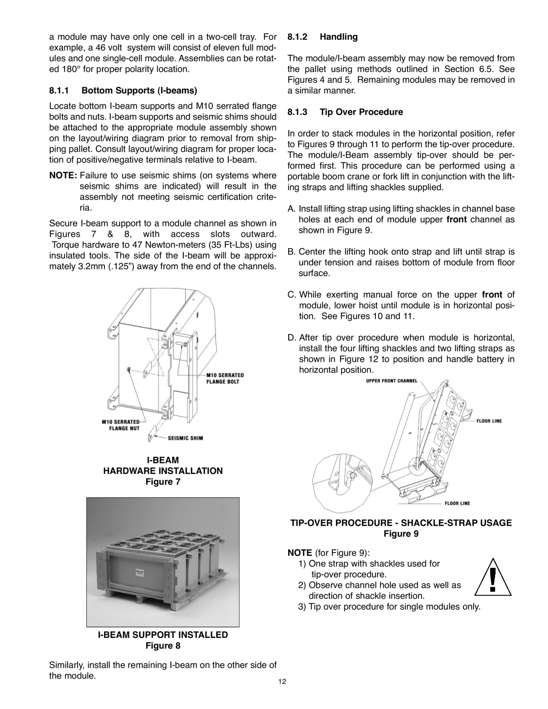
I-BEAM
HARDWARE INSTALLATION
Figure 7
|
|
Figure 8 |
|
Similarly, install the remaining | 12 |
the module. |
8.1.2 Handling
The
8.1.3 Tip Over Procedure
In order to stack modules in the horizontal position, refer to Figures 9 through 11 to perform the
A. Install lifting strap using lifting shackles in channel base holes at each end of module upper front channel as shown in Figure 9.
B. Center the lifting hook onto strap and lift until strap is under tension and raises bottom of module from floor surface.
C. While exerting manual force on the upper front of module, lower hoist until module is in horizontal posi- tion. See Figures 10 and 11.
D. After tip over procedure when module is horizontal, install the four lifting shackles and two lifting straps as shown in Figure 12 to position and handle battery in horizontal position.
TIP-OVER PROCEDUREFigure- SHACKLE9 -STRAP USAGE
NOTE (for Figure 9):
1) One strap with shackles used for
2) Observe channel hole used as well as direction of shackle insertion.
3) Tip over procedure for single modules only.