3.4DRIVE WHEELS
3.4.3Check air pressure in drive tires; recommended pressure is
3.5MOWER DECK INSTALLATION
3.5.1Release the wheel drive system by opening the drive wheel release valves (See 4.1.11). Roll the tractor to the mower deck assembly and allow the tractor assembly to tip backward until the rear of the engine deck contacts the ground.
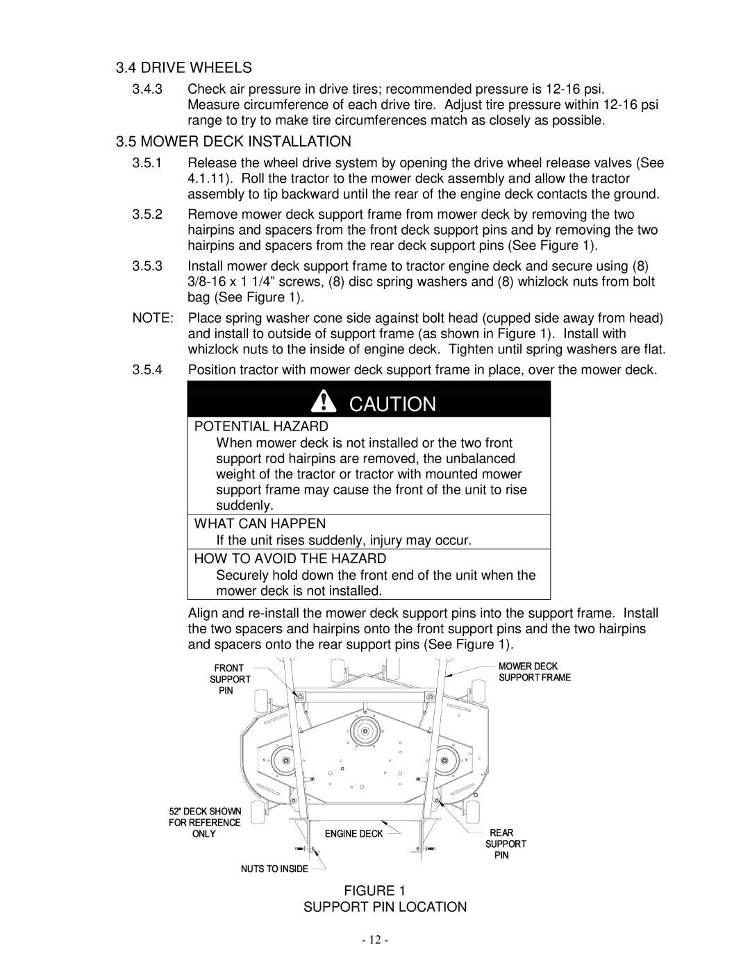
3.5.2Remove mower deck support frame from mower deck by removing the two hairpins and spacers from the front deck support pins and by removing the two hairpins and spacers from the rear deck support pins (See Figure 1).
3.5.3Install mower deck support frame to tractor engine deck and secure using (8)
NOTE: Place spring washer cone side against bolt head (cupped side away from head) and install to outside of support frame (as shown in Figure 1). Install with whizlock nuts to the inside of engine deck. Tighten until spring washers are flat.
3.5.4Position tractor with mower deck support frame in place, over the mower deck.
CAUTION
POTENTIAL HAZARD
♦When mower deck is not installed or the two front support rod hairpins are removed, the unbalanced weight of the tractor or tractor with mounted mower support frame may cause the front of the unit to rise suddenly.
WHAT CAN HAPPEN
♦If the unit rises suddenly, injury may occur.
HOW TO AVOID THE HAZARD
♦Securely hold down the front end of the unit when the mower deck is not installed.
Align and
FIGURE 1
SUPPORT PIN LOCATION
- 12 -