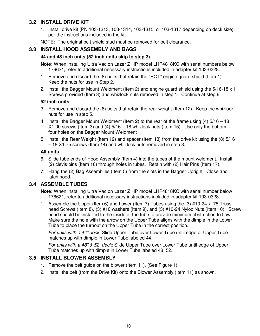
Ultra Vac specifications
The Exmark Ultra Vac is a powerful and efficient vacuum system designed to streamline lawn maintenance for both professionals and homeowners. This high-performance attachment is compatible with Exmark mowers, transforming them into versatile leaf collection and debris management tools that enhance productivity and maintain a clean landscape.One of the main features of the Exmark Ultra Vac is its robust vacuuming capability. With a large capacity collection system, this vacuum can handle a significant volume of leaves, grass clippings, and other debris, reducing the frequency of emptying during operation. The unit is equipped with a heavy-duty impeller, which provides exceptional suction power, ensuring that even wet leaves and dense clippings are effectively collected without clogging.
The Ultra Vac system is designed for easy installation and removal, making it convenient for users to switch between mowing and vacuuming modes. It integrates seamlessly with various Exmark mowers, ensuring a perfect fit that does not compromise the mower's performance. This versatility is particularly valuable for lawn care professionals who require adaptability for different tasks and conditions.
Another notable technology in the Ultra Vac is its advanced airflow design. This feature optimizes the suction flow, allowing for efficient vacuuming while maintaining the overall performance of the mower. The aerodynamic design helps to reduce noise levels, providing a quieter operation which is particularly beneficial in residential areas or noise-sensitive environments.
The Ultra Vac also boasts user-friendly features such as an adjustable chute, allowing operators to customize the height and angle of the vacuuming path. This flexibility ensures that users can effectively collect debris in various terrains and conditions. Additionally, the unit's durable construction means it can withstand the rigors of regular use, offering reliability and longevity.
Maintenance is made easy with the Ultra Vac, thanks to accessible access points and a user-friendly design. Routine checks and cleaning can be performed without requiring extensive disassembly, making it practical for busy schedules.
In summary, the Exmark Ultra Vac is a powerful, efficient, and user-friendly vacuuming system that enhances the capabilities of Exmark mowers. Its robust features, advanced technologies, and durable design make it an essential tool for anyone looking to maintain a pristine landscape with minimal effort. Whether for professional use or residential upkeep, the Ultra Vac stands out as a reliable solution for effective debris management.
