Manuals
/
Extron electronic
/
Home Audio
/
Home Theater System
Extron electronic
DP DA2
manual
DIP switches, Summary
Models:
DP DA2
1
13
30
30
Download
30 pages
49.24 Kb
10
11
12
13
14
15
16
17
Page 13
Image 13
Page 12
Page 14
Page 13
Image 13
Page 12
Page 14
Contents
User Guide
DP DA2
DisplayPort
Distribution Amplifier
Safety Instructions English
Safety Instructions
Instructions de sécurité Français
Sicherheitsanweisungen Deutsch
FCC Class A Notice
Specifications Availability
Copyright
Trademarks
Conventions Used in this Guide
Software Commands
Notifications
Safety Instructions
Contents
DP DA2 Contents
Introduction
DP DA2 Features
About the DP DA2
About the DP DA2 DP DA2 Features
TouchLink
Application Diagram
TCP/IP
Rear Panel
Panel Features
Front Panel
Power Supply
Rear Panel Features
Function
Display Port Connectors
EDID Minder
Dual Mode DisplayPort
EDID Store push button and LED
Recording EDID
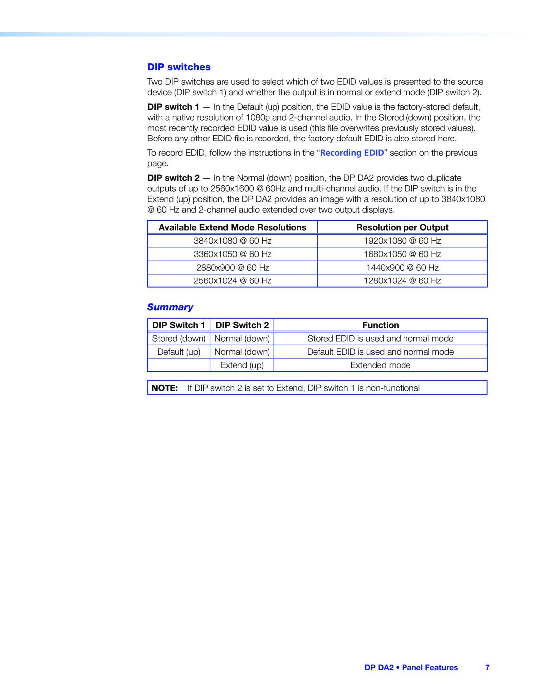
Summary
DIP switches
Mute Control
RS-232Control
Host PC Pin
DP DA2 Pin
Power LED
Front Panel Features
Config USB Port
Connecting to the USB Port
DP DA2 Panel Features
Figure 7. Installing the Software Automatically
Signal LEDs
Signal and HDCP LEDs
HDCP LEDs
Setup
Introduction to SIS
SIS Commands
Introduction to SIS Symbols Used in this Guide
•Error Messages
Error Messages
Symbols Used in this Guide
Table 1. ASCII to HEX Conversion Table
Command and Response Table for SIS Commands
Updating Firmware
Downloading and Installing Firmware Loader
Downloading and Installing Firmware Loader
Downloading DP DA2 Firmware
Figure 9. Firmware Link on the Download Tab
Downloading DP DA2 Firmware
Figure 10. Opening Firmware Loader
Loading the Firmware to the DP DA2
DP DA2 Updating Firmware
DP DA2 Updating Firmware
DP DA2 Updating Firmware
Resetting Firmware to the Factory Default Version
Included Parts
Reference Information
Optional Parts
DP DA2 Setup Guide
Rack Mounting Procedure
Desktop Placement
Mounting
Rack Mounting
Extron Warranty
Top
Page
Image
Contents