Receiver Connections


POWER

SIG

LINK

OVER DTP

OUTPUTS


12V


DVI-D

0.8 A MAX


RS-232


IR


DTP IN

Tx Rx

G

Tx Rx


Rear 11

7

10

Front

8

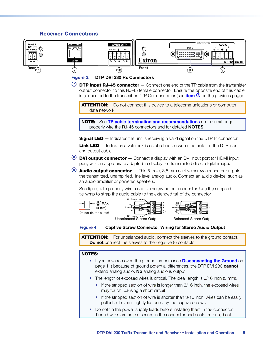
Figure 3. DTP DVI 230 Rx Connectors

AUDIO

L R

DTP DVI 230 Rx

9

GDTP Input RJ-45 connector — Connect one end of the TP cable from the transmitter output connector to this RJ-45 female connector. Ensure the opposite end of this cable is connected to the transmitter DTP Out connector (see item E on the previous page).

ATTENTION: Do not connect this device to a telecommunications or computer data network.

NOTE: See TP cable termination and recommendations on the next page to properly wire the RJ-45 connectors and for detailed NOTES.

Signal LED — Indicates the unit is receiving a valid signal on the DTP In connector.

Link LED — Indicates a valid link is established between the units on the DTP input and output cable.

HDVI output connector — Connect a display with an DVI input port (or HDMI input port, with an appropriate adapter) to display the transmitted direct digital image.

IAudio output connector — This 5-pole, 3.5 mm captive screw connector outputs the transmitted, unamplified, line level analog audio. Connect an audio device, such as an audio amplifier or powered speakers.

See figure 4 to properly wire a captive screw output connector. Use the supplied tie-wrap to strap the audio cable to the extended tail of the connector.

Do not tin the wires!

No Ground Here

Tip

Sleeves

Tip

L

Tip


Ring


Sleeves

R

Tip

Ring


No Ground Here

Balanced Stereo Outp

Unbalanced Stereo Output

Figure 4. Captive Screw Connector Wiring for Stereo Audio Output

ATTENTION: For unbalanced audio, connect the sleeves to the ground contact. Do not connect the sleeves to the negative (-) contacts.

NOTES:

If you have removed the ground jumpers (see Disconnecting the Ground on page 11) because of ground potential differences, the DTP DVI 230 cannot extend analog audio. No analog audio is output.

The length of exposed wires is critical. The ideal length is 3/16 inch (5 mm).

If the stripped section of wire is longer than 3/16 inch, the exposed wires may touch, causing a short circuit.

If the stripped section of wire is shorter than 3/16 inch, wires can be easily pulled out even if tightly fastened by the captive screws.

Do not tin the power supply leads before installing them in the connector. Tinned wires are not as secure in the connector and could be pulled out.

DTP DVI 230 Tx/Rx Transmitter and Receiver • Installation and Operation

5

Page 11
Image 11
Extron electronic manual Receiver Connections, DTP DVI 230 Rx Connectors

DTP DVI 230 specifications

The Extron DTP DVI 230 is a powerful and versatile solution designed for the transmission of high-quality DVI video signals over long distances. This compact device is perfect for a range of AV applications, from corporate environments to educational settings, ensuring that high-resolution video is delivered without compromise.

One of the key features of the DTP DVI 230 is its ability to transmit DVI signals up to 230 feet (70 meters) over a single Cat 6 cable. This capability eliminates the need for bulky cables, allowing for a cleaner and more organized installation. Additionally, the device supports both DVI-D and DVI-I formats, enabling compatibility with a wide range of video sources and displays.

The DTP DVI 230 excels in video quality, supporting resolutions up to 1920 x 1200 at 60 Hz, as well as 1080p, which ensures that users can enjoy a crystal-clear viewing experience. This makes it an ideal choice for applications that demand high-definition video, such as presentations, video conferencing, and digital signage.

Another notable technology integrated into the DTP DVI 230 is its robust signal processing capabilities. The device uses advanced signal equalization to maintain the integrity of the video signal over long distances. This ensures that signal degradation and distortion are minimized, providing a reliable and consistent output that professionals can depend on.

The DTP DVI 230 features a user-friendly design with an intuitive interface. It includes LED indicators that provide real-time status feedback for power and signal presence, making it easy for users to monitor the device’s operation. Moreover, the compact form factor allows for flexible installation options, whether it is rack-mounted or placed in an AV cabinet.

In terms of compatibility, the Extron DTP platform enables seamless integration with other Extron products such as matrix switchers and control systems. This makes it an integral part of sophisticated AV system designs, allowing for streamlined operation and control across different devices.

Overall, the Extron DTP DVI 230 is an exceptional choice for any AV professional seeking a reliable, high-performance solution for long-distance DVI signal transmission. With its impressive feature set, advanced technologies, and ease of integration, it stands out as a top-tier option in the market.