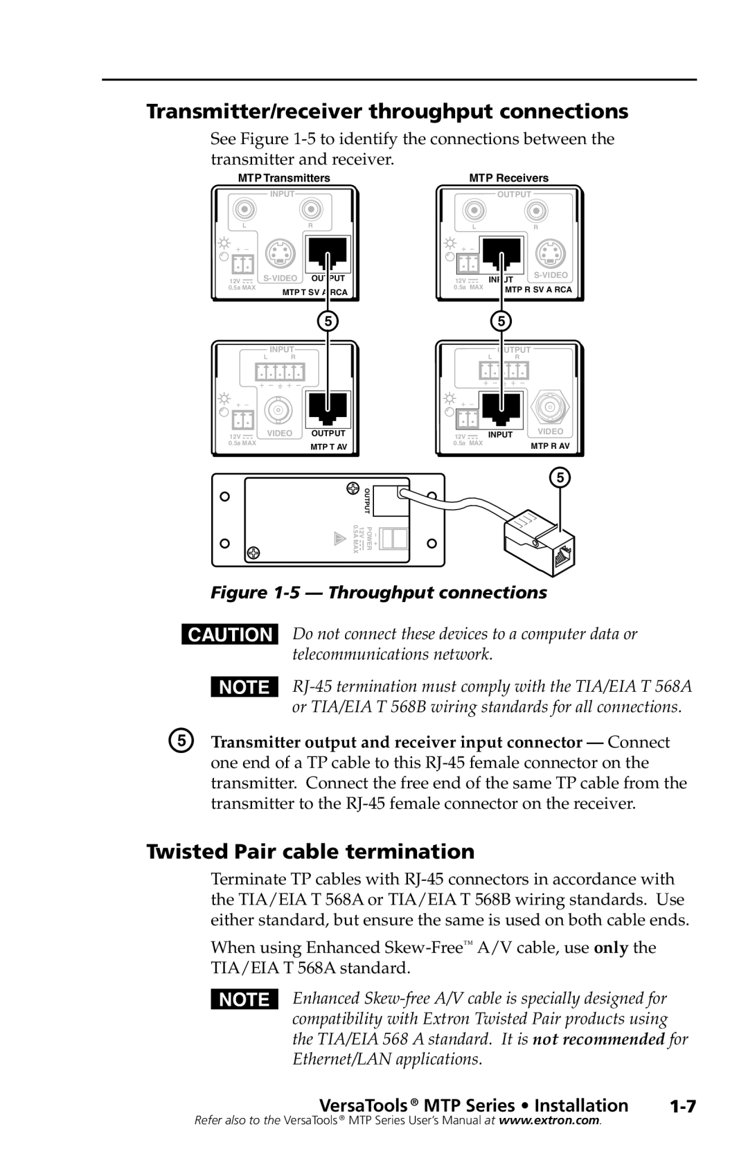
Transmitter/receiver throughput connections
See Figure
MTP Transmitters
INPUT
LR
|
|
|
|
| |
|
|
|
|
| |
12V |
|
| OUTPUT | ||
0.5a MAX | MTP T SV A RCA | ||||
|
|
|
| ||
E
INPUT
L R
12V | VIDEO | OUTPUT |
0.5a MAX |
| MTP T AV |
|
|
MTP Receivers
|
| OUTPUT |
|
| L |
| R |
12V |
| INPUT | |
|
| ||
0.5a | MAX | MTP R SV A RCA | |
| E |
|
| OUTPUT | |
| L | R |
12V | INPUT | VIDEO |
| ||
0.5a | MAX | MTP R AV |
|
| |
+ − OUTPUT POWER 12V 0.5A MAX![]()
![]()
![]()
E
Figure 1-5 — Throughput connections
CDo not connect these devices to a computer data or telecommunications network.
| N |
| or TIA/EIA T 568B wiring standards for all connections. |
E | Transmitter output and receiver input connector — Connect |
| one end of a TP cable to this |
| transmitter. Connect the free end of the same TP cable from the |
| transmitter to the |
Twisted Pair cable termination
Terminate TP cables with
When using Enhanced
NEnhanced
VersaTools ® MTP Series • Installation |
Refer also to the VersaTools ® MTP Series User’s Manual at www.extron.com.