Installation, cont’d
Receiver output connections
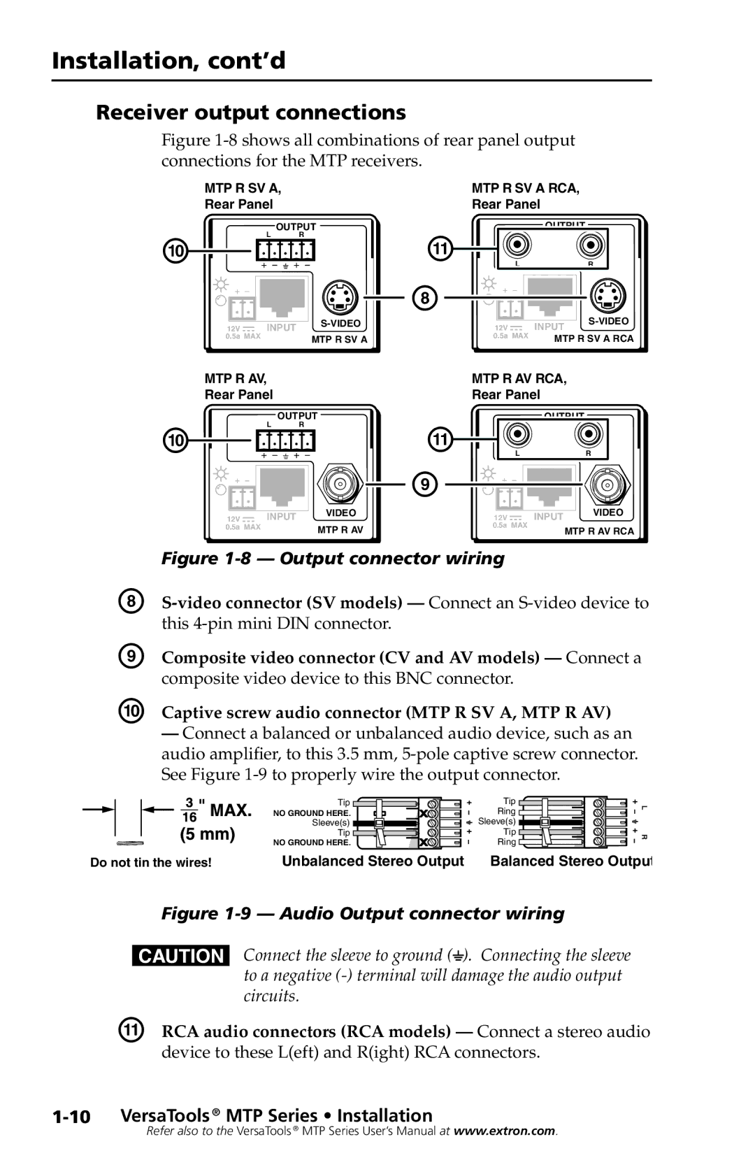
Figure 1-8 shows all combinations of rear panel output connections for the MTP receivers.
MTP R SV A, | MTP R SV A RCA, |
Rear Panel | Rear Panel |
|
| L | OUTPUT |
|
| OUTPUT |
| |
J |
|
| R | K |
|
|
| |
|
|
|
| L |
| R | ||
|
|
|
|
| H |
|
| |
12V |
| INPUT | 12V |
| INPUT | |||
|
|
|
| |||||
0.5a | MAX |
|
| MTP R SV A | 0.5a | MAX | MTP R SV A RCA | |
MTP R AV, | MTP R AV RCA, |
Rear Panel | Rear Panel |
|
| OUTPUT |
|
| OUTPUT |
J | L | R | K | L | R |
|
|
| I |
|
|
|
|
|
|
|
| VIDEO |
|
|
|
|
|
| VIDEO |
| 12V |
|
| INPUT | 12V |
|
| INPUT |
| ||||
|
|
|
|
|
|
|
| ||||||
| 0.5a | MAX |
| MTP R AV | 0.5a | MAX |
| MTP R AV RCA | |||||
|
|
|
|
|
|
|
|
|
|
| |||
| Figure |
|
|
|
|
| |||||||
H |
| ||||||||||||
| this |
|
|
|
|
|
|
| |||||
I | Composite video connector (CV and AV models) — Connect a | ||||||||||||
| composite video device to this BNC connector. |
|
|
| |||||||||
J Captive screw audio connector (MTP R SV A, MTP R AV)
—Connect a balanced or unbalanced audio device, such as an audio amplifier, to this 3.5 mm,
Tip | Tip |
NO GROUND HERE. | Ring |
Sleeve(s) | Sleeve(s) |
Tip | Tip |
NO GROUND HERE. | Ring |
L R
Do not tin the wires! | Unbalanced Stereo Output | Balanced Stereo Output |
Figure 1-9 — Audio Output connector wiring
CConnect the sleeve to ground (_). Connecting the sleeve to a negative
K | RCA audio connectors (RCA models) — Connect a stereo audio |
| device to these L(eft) and R(ight) RCA connectors. |
Refer also to the VersaTools ® MTP Series User’s Manual at www.extron.com.
