Installation, cont’d
Power connection (all models)
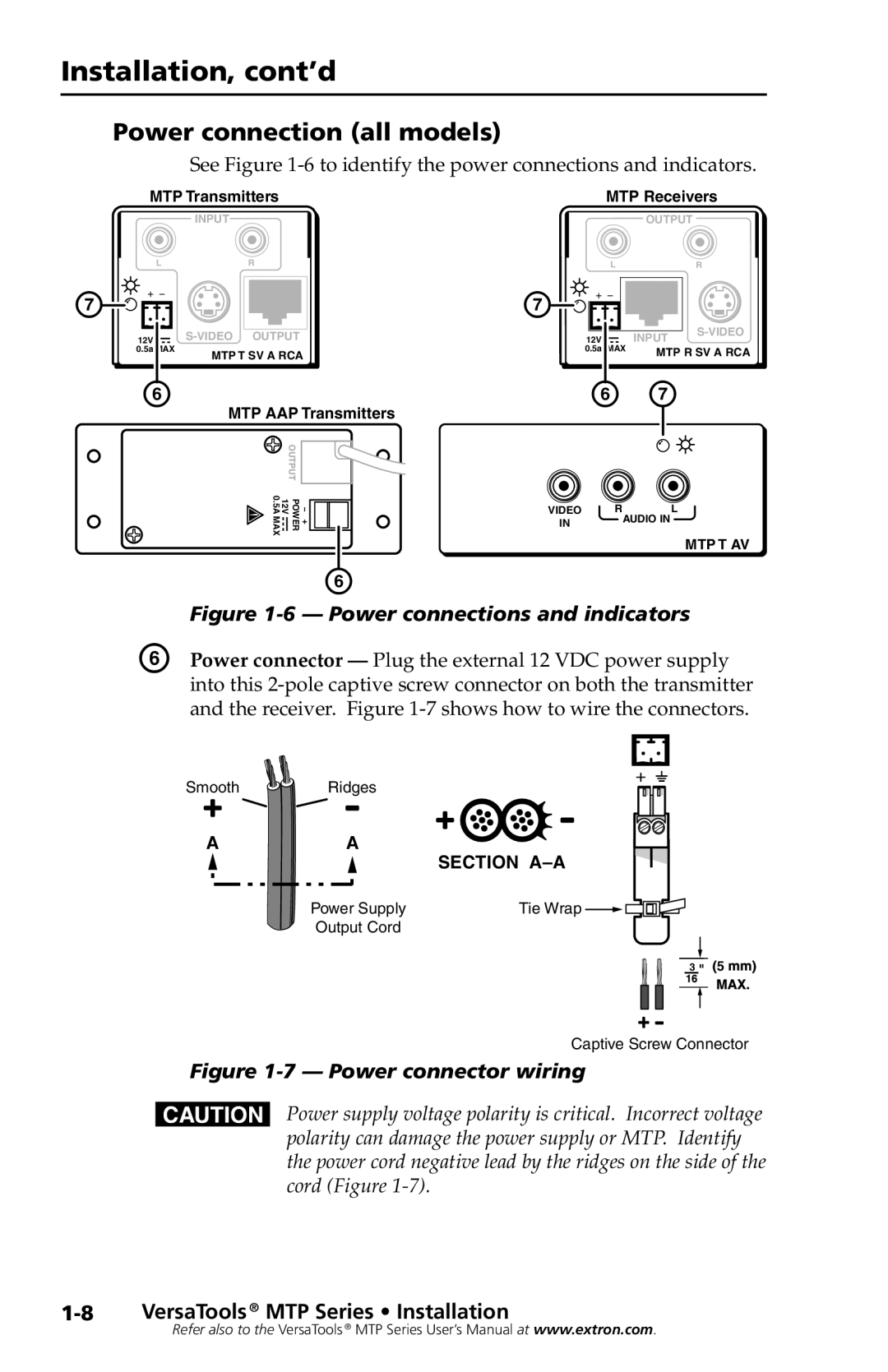
See Figure 1-6 to identify the power connections and indicators.
MTP Transmitters
INPUT
MTP Receivers
OUTPUT
L | R |
| L |
| R |
G |
| G |
|
|
|
12V | 12V |
| INPUT | ||
|
| ||||
0.5a MAX | MTP T SV A RCA | 0.5a | MAX | MTP R SV A RCA | |
|
|
|
|
| |
F | MTP AAP Transmitters | F G |
| ||
+ − OUTPUT POWER 12V 0.5A MAX![]()
![]()
![]()
F
VIDEO | RAUDIO INL |
IN |
|
MTP T AV
Figure 1-6 — Power connections and indicators
F | Power connector — Plug the external 12 VDC power supply |
| into this |
| and the receiver. Figure |
Smooth | Ridges | + _ |
|
A | A |
SECTION
Power Supply | Tie Wrap |
Output Cord |
|
3 ![]()
![]() 5
5 ![]()
![]()
Captive Screw Connector
Figure 1-7 — Power connector wiring
CPower supply voltage polarity is critical. Incorrect voltage polarity can damage the power supply or MTP. Identify the power cord negative lead by the ridges on the side of the cord (Figure
Refer also to the VersaTools ® MTP Series User’s Manual at www.extron.com.