Installation, cont’d

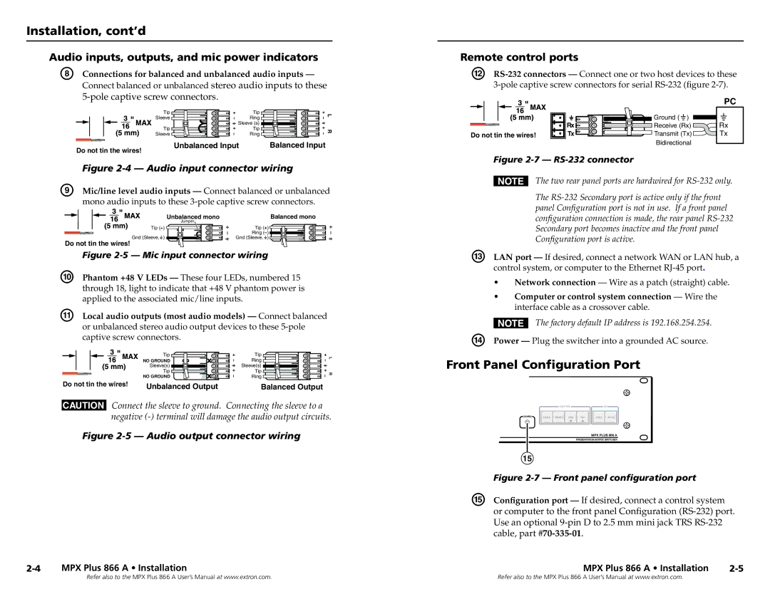
Audio inputs, outputs, and mic power indicators

H Connections for balanced and unbalanced audio inputs —


Connect balanced or unbalanced stereo audio inputs to these


5-pole captive screw connectors.


Tip

Tip

L

Sleeve

Ring


Sleeve (s)


Tip

Tip

R

Sleeve

Ring


Do not tin the wires!

Unbalanced Input

Balanced Input


Figure 2-4 — Audio input connector wiring

I

Mic/line level audio inputs — Connect balanced or unbalanced


mono audio inputs to these 3-pole captive screw connectors.


Unbalanced mono

Balanced mono


Jumper


Tip (+)

Tip (+)


Ring ()

Gnd (Sleeve,

)

Gnd (Sleeve, )

Do not tin the wires!


Figure 2-5 — Mic input connector wiring

J

Phantom +48 V LEDs — These four LEDs, numbered 15


through 18, light to indicate that +48 V phantom power is


applied to the associated mic/line inputs.

K

Local audio outputs (most audio models) — Connect balanced


or unbalanced stereo audio output devices to these 5-pole


captive screw connectors.

Tip

Tip

L

NO GROUND

Ring


Sleeve(s)

Sleeve(s)


Tip

Tip

R

NO GROUND

Ring


Do not tin the wires!

Unbalanced Output

Balanced Output

CAUTION Connect the sleeve to ground. Connecting the sleeve to a negative (-) terminal will damage the audio output circuits.

Figure 2-5 — Audio output connector wiring

2-4 MPX Plus 866 A • Installation

Remote control ports

L

RS-232 connectors — Connect one or two host devices to these


3-pole captive screw connectors for serial RS-232 (figure 2-7).


PC


Ground ( )


Rx

Receive (Rx)

Rx

Do not tin the wires!

Tx

Transmit (Tx)

Tx


Bidirectional


Figure 2-7RS-232 connector


N The two rear panel ports are hardwired for RS-232 only.


The RS-232 Secondary port is active only if the front


panel Configuration port is not in use. If a front panel


configuration connection is made, the rear panel RS-232


Secondary port becomes inactive and the front panel


Configuration port is active.

M

LAN port — If desired, connect a network WAN or LAN hub, a


control system, or computer to the Ethernet RJ-45 port.


Network connection — Wire as a patch (straight) cable.


Computer or control system connection — Wire the


interface cable as a crossover cable.

N The factory default IP address is 192.168.254.254. N Power — Plug the switcher into a grounded AC source.

Front Panel Configuration Port


CONTROL


I/O

CONFIG

ENTER PRESET

VIEW

ESC

VIDEO

AUDIO


MPX PLUS 866 A


PRESENTATION MATRIX SWITCHER


15


Figure 2-7 — Front panel configuration port


O

Configuration port — If desired, connect a control system


or computer to the front panel Configuration (RS-232) port.


Use an optional 9-pin D to 2.5 mm mini jack TRS RS-232


cable, part #70-335-01.


MPX Plus 866 A • Installation

2-5

Refer also to the MPX Plus 866 A User’s Manual at www.extron.com.

Refer also to the MPX Plus 866 A User’s Manual at www.extron.com.

Page 9
Image 9
Extron electronic MPX Plus 866 A, N 60-796-01 Installation, cont’d, Front Panel Configuration Port, Remote control ports

MPX Plus 866 A, N 60-796-01 specifications

The Extron MPX Plus 866 A is a powerful multimedia presentation switcher designed to meet the needs of modern AV environments. This advanced device simplifies the management of multiple audio and video sources, providing seamless control and connectivity in various settings such as conference rooms, classrooms, and auditoriums.

One of the key features of the MPX Plus 866 A is its ability to handle a wide range of video formats. It supports both HDMI and analog video, allowing for compatibility with different devices. This versatility ensures users can connect laptops, projectors, and other AV equipment without any issues, making it ideal for mixed-use environments where various technologies coexist.

With an 8x8 matrix design, the MPX Plus 866 A can route up to eight different input sources to eight output destinations. This feature enables users to select and switch between sources quickly and efficiently, enhancing the overall presentation experience. Additionally, the device incorporates Extron's high-performance scaling technology, which ensures that video signals are processed with exceptional clarity and detail, regardless of resolution.

Another noteworthy characteristic of the MPX Plus 866 A is its built-in audio capabilities. The switcher includes a comprehensive audio mixer with support for both analog and digital audio signals. This allows users to integrate and control audio sources effectively, ensuring that sound quality matches the visual experience. Furthermore, it features advanced audio processing tools, including equalization and filtering functions, to enhance audio output in any environment.

The MPX Plus 866 A also emphasizes ease of use and accessibility. Its user-friendly interface, combined with an intuitive control system, allows operators to navigate the device with minimal training. Additionally, the switcher supports various control options, including RS-232 and Ethernet, enabling integration into larger AV control systems for centralized management.

In summary, the Extron MPX Plus 866 A stands out as a versatile and reliable multimedia presentation switcher. Its extensive range of input and output options, advanced scaling and audio processing technologies, and emphasis on user-friendly design make it an exceptional choice for any professional AV installation. Whether in an educational setting or corporate environment, the MPX Plus 866 A ensures seamless connectivity and high-quality performance, meeting the demands of today’s multimedia presentations.