Installation Manual for DiBos Video System
Connections (continued)
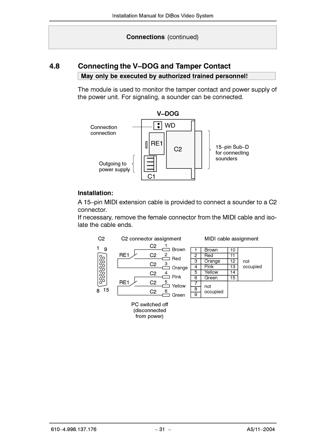
4.8Connecting the V–DOG and Tamper Contact
May only be executed by authorized trained personnel!
The module is used to monitor the tamper contact and power supply of the power unit. For signaling, a sounder can be connected.
|
|
Connection | WD |
connection |
|
RE1
Outgoing to power supply
C1
Installation:
C2
A
If necessary, remove the female connector from the MIDI cable and iso- late the cable ends.
C2 | C2 connector assignment | MIDI cable assignment |
1 | 9 | C2 |
| ||
| RE1 | C2 |
|
| C2 |
|
| C2 |
| RE1 | C2 |
8 | 15 | C2 |
1 | Brown |
|
| |
| 1 | Brown | ||
2 | ||||
Red | 2 | Red | ||
3 | 3 | Orange | ||
| ||||
Orange | 4 | Pink | ||
| ||||
4 | Pink | 5 | Yellow | |
5 | 6 | Green | ||
Yellow | 7 | not | ||
6 | 8 | |||
| occupied | |||
Green | 9 | |||
|
| |||
|
|
10
11
12not
13occupied
14
15
PC switched off
(disconnected
from power)
– 31 – |