Installation Manual for DiBos Video System
Configuration (continued)
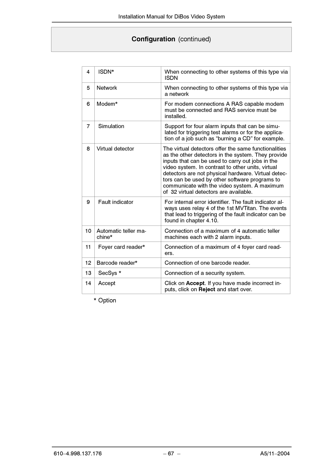
4 | ISDN* | When connecting to other systems of this type via |
|
| ISDN |
|
|
|
5 | Network | When connecting to other systems of this type via |
|
| a network |
|
|
|
6 | Modem* | For modem connections A RAS capable modem |
|
| must be connected and RAS service must be |
|
| installed. |
|
|
|
7 | Simulation | Support for four alarm inputs that can be simu- |
|
| lated for triggering test alarms or for the applica- |
|
| tion of a job such as “burning a CD” for example. |
|
|
|
8 | Virtual detector | The virtual detectors offer the same functionalities |
|
| as the other detectors in the system. They provide |
|
| inputs that can be used to carry out jobs in the |
|
| video system. In contrast to other units, virtual |
|
| detectors are not physical hardware. Virtual detec- |
|
| tors can be used by other software programs to |
|
| communicate with the video system. A maximum |
|
| of 32 virtual detectors are available. |
|
|
|
9 | Fault indicator | For internal error identifier. The fault indicator al- |
|
| ways uses relay 4 of the 1st MVTitan. The events |
|
| that lead to triggering of the fault indicator can be |
|
| found in chapter 4.10. |
|
|
|
10 | Automatic teller ma- | Connection of a maximum of 4 automatic teller |
| chine* | machines each with 2 alarm inputs. |
|
|
|
11 | Foyer card reader* | Connection of a maximum of 4 foyer card read- |
|
| ers. |
|
|
|
12 | Barcode reader* | Connection of one barcode reader. |
|
|
|
13 | SecSys * | Connection of a security system. |
|
|
|
14 | Accept | Click on Accept. If you have made incorrect in- |
|
| puts, click on Reject and start over. |
|
|
|
* Option
| – 67 – |