Installation Manual for DiBos Video System
Configuration (continued)
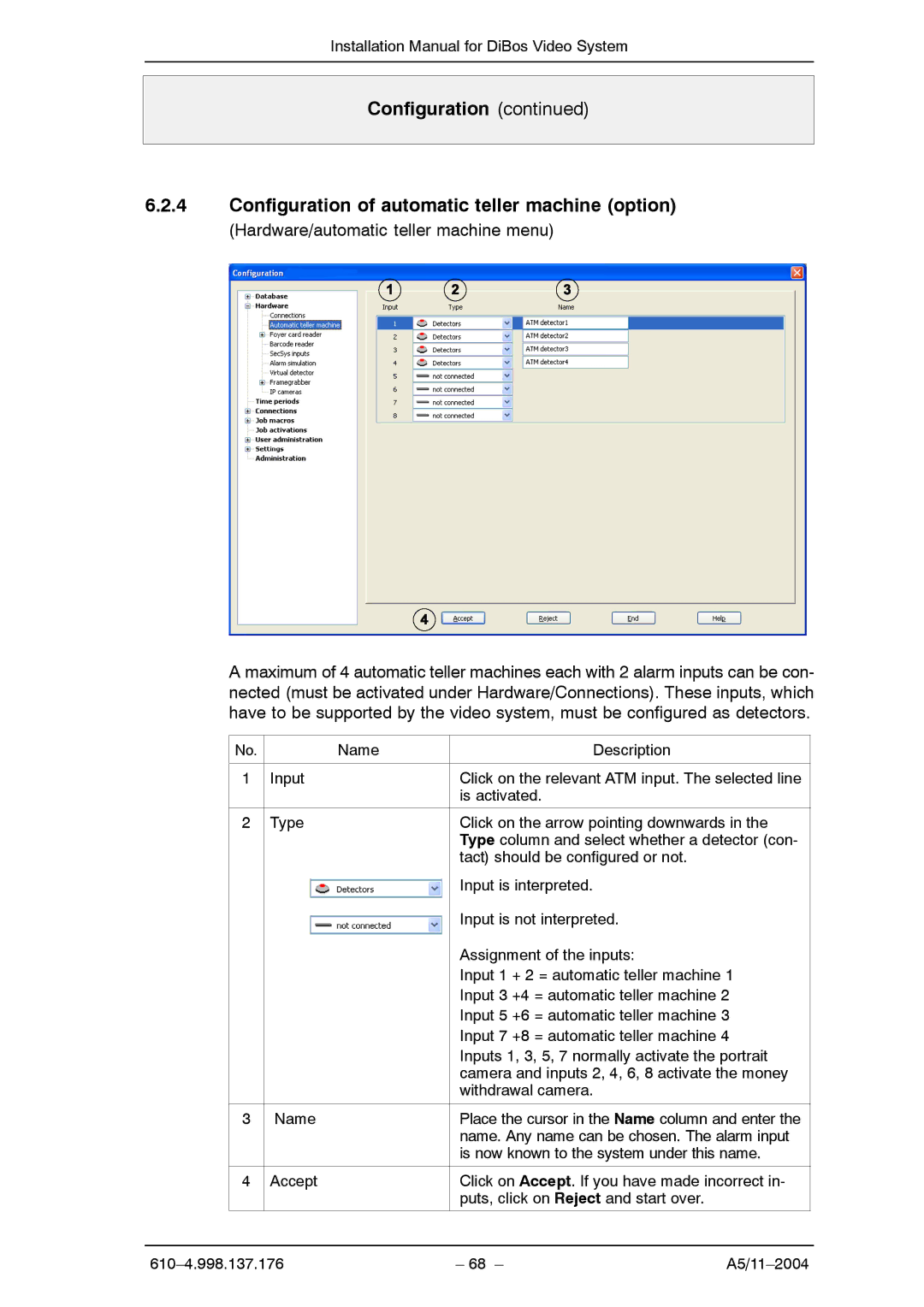
6.2.4Configuration of automatic teller machine (option)
(Hardware/automatic teller machine menu)
A maximum of 4 automatic teller machines each with 2 alarm inputs can be con- nected (must be activated under Hardware/Connections). These inputs, which have to be supported by the video system, must be configured as detectors.
No. | Name | Description |
|
|
|
1 | Input | Click on the relevant ATM input. The selected line |
|
| is activated. |
|
|
|
2 | Type | Click on the arrow pointing downwards in the |
|
| Type column and select whether a detector (con- |
|
| tact) should be configured or not. |
|
| Input is interpreted. |
|
| Input is not interpreted. |
|
| Assignment of the inputs: |
|
| Input 1 + 2 = automatic teller machine 1 |
|
| Input 3 +4 = automatic teller machine 2 |
|
| Input 5 +6 = automatic teller machine 3 |
|
| Input 7 +8 = automatic teller machine 4 |
|
| Inputs 1, 3, 5, 7 normally activate the portrait |
|
| camera and inputs 2, 4, 6, 8 activate the money |
|
| withdrawal camera. |
|
|
|
3 | Name | Place the cursor in the Name column and enter the |
|
| name. Any name can be chosen. The alarm input |
|
| is now known to the system under this name. |
|
|
|
4 | Accept | Click on Accept. If you have made incorrect in- |
|
| puts, click on Reject and start over. |
|
|
|
– 68 – |