Installation Manual for DiBos Video System
Connections (continued)
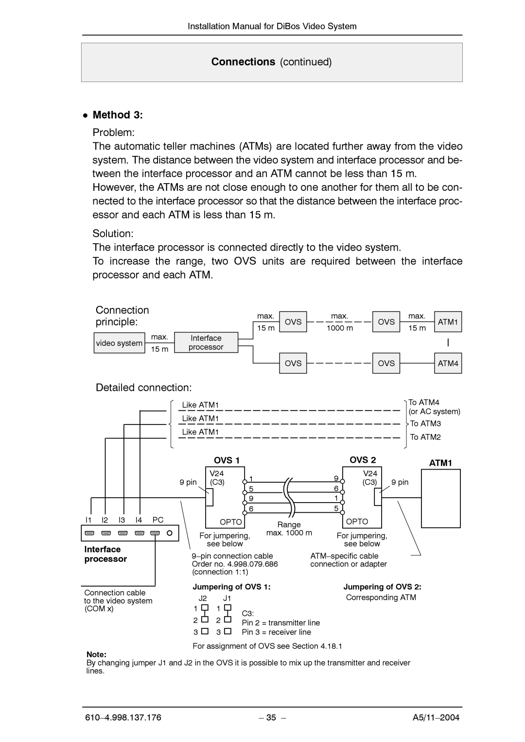
DMethod 3:
Problem:
The automatic teller machines (ATMs) are located further away from the video system. The distance between the video system and interface processor and be- tween the interface processor and an ATM cannot be less than 15 m.
However, the ATMs are not close enough to one another for them all to be con- nected to the interface processor so that the distance between the interface proc- essor and each ATM is less than 15 m.
Solution:
The interface processor is connected directly to the video system.
To increase the range, two OVS units are required between the interface processor and each ATM.
Connection principle:
video system | max. | Interface |
|
| |||
15 m | processor |
| |
| |||
|
|
|
|
Detailed connection:
Like ATM1
Like ATM1
Like ATM1
max.
15 m
OVS
OVS
max.
1000 m
OVS | max. | ATM1 | |
| |||
15 m | |||
|
|
OVS ![]() ATM4
ATM4
To ATM4
(or AC system) To ATM3
To ATM2
|
| OVS 1 |
|
|
|
| OVS 2 | ATM1 | |
|
| V24 | 1 |
|
| 9 | V24 |
| |
| 9 pin | (C3) |
|
| (C3) | 9 pin | |||
| 5 |
|
| 6 | |||||
|
|
|
|
|
|
|
| ||
|
|
|
| 9 |
|
| 1 |
|
|
|
|
|
| 6 |
|
| 5 |
|
|
I1 I2 I3 I4 | PC | OPTO | Range |
|
| OPTO |
| ||
|
| For jumpering, | max. 1000 m | For jumpering, |
| ||||
Interface |
| see below |
|
|
| see below |
| ||
| |||||||||
processor |
| ||||||||
| Order no. 4.998.079.686 | connection or adapter |
| ||||||
| (connection 1:1) |
|
|
|
|
| |||
Connection cable | Jumpering of OVS 1: |
|
| Jumpering of OVS 2: | |||||
| J2 | J1 |
|
|
|
| Corresponding ATM | ||
to the video system |
|
|
|
|
| ||||
(COM x) | 1 | 1 |
| C3: |
|
|
|
|
|
| 2 | 2 |
|
|
|
|
|
| |
|
| Pin 2 = transmitter line |
|
|
| ||||
|
|
|
|
|
|
| |||
| 3 | 3 |
| Pin 3 = receiver line |
|
|
| ||
For assignment of OVS see Section 4.18.1
Note:
By changing jumper J1 and J2 in the OVS it is possible to mix up the transmitter and receiver lines.
| – 35 – |