Installation Manual for DiBos Video System
Connections (continued)
4.12Connecting the Barcode Reader
4.12.1Barcode Reader V3300–N
Only the barcode readers listed below should be used. With other types of barcode readers, you must check whether their protocol matches that of the video system.
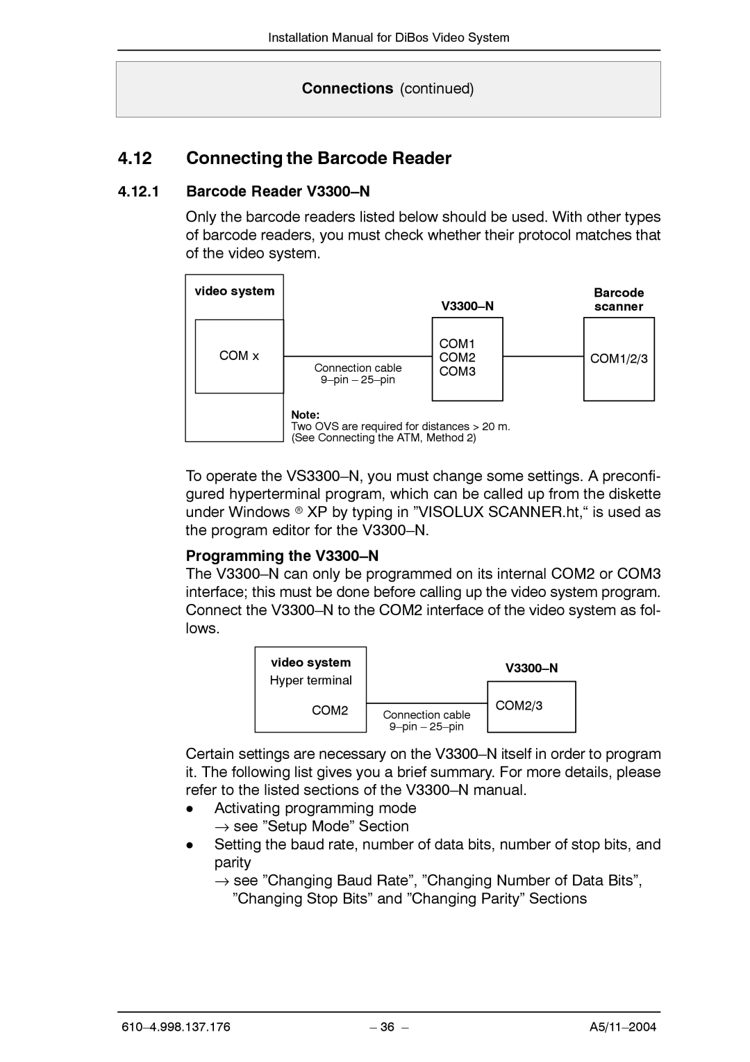
video system
COM x
|
|
|
|
|
|
| COM1 |
|
Connection cable | COM2 |
|
| ||
COM3 |
| |
|
| |
|
|
|
Note:
Two OVS are required for distances > 20 m. (See Connecting the ATM, Method 2)
Barcode scanner
COM1/2/3
To operate the
Programming the V3300–N
The
video system Hyper terminal
COM2
Connection cable
COM2/3
Certain settings are necessary on the
DActivating programming mode
→see ”Setup Mode” Section
DSetting the baud rate, number of data bits, number of stop bits, and parity
→see ”Changing Baud Rate”, ”Changing Number of Data Bits”, ”Changing Stop Bits” and ”Changing Parity” Sections
| – 36 – |