Installation Manual for DiBos Video System
Connections (continued)
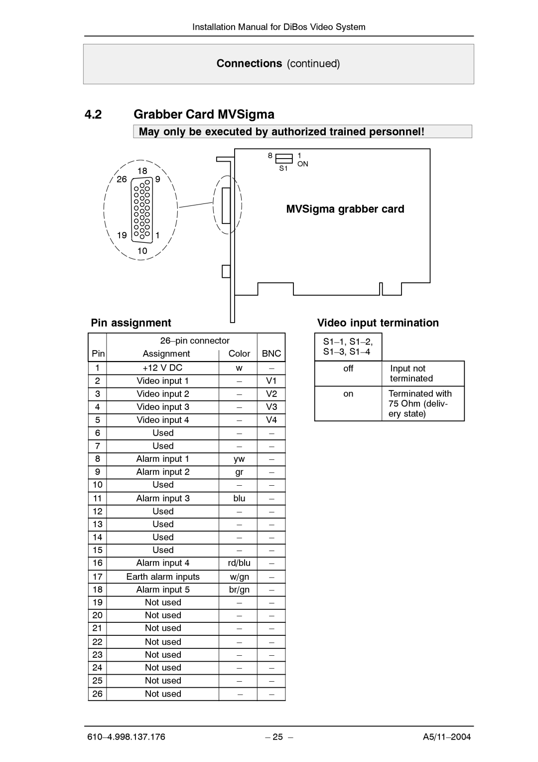
4.2Grabber Card MVSigma
May only be executed by authorized trained personnel!
26 18 9
191
10
Pin assignment
81
S1 ON
MVSigma grabber card
Video input termination
|
| |||
Pin | Assignment |
| Color | BNC |
| ||||
|
|
|
|
|
1 | +12 V DC |
| w | – |
|
|
|
|
|
2 | Video input 1 |
| – | V1 |
|
|
|
|
|
3 | Video input 2 |
| – | V2 |
|
|
|
|
|
4 | Video input 3 |
| – | V3 |
5 | Video input 4 |
| – | V4 |
|
|
|
|
|
6 | Used |
| – | – |
|
|
|
|
|
7 | Used |
| – | – |
|
|
|
|
|
8 | Alarm input 1 |
| yw | – |
|
|
|
|
|
9 | Alarm input 2 |
| gr | – |
10 | Used |
| – | – |
|
|
|
|
|
11 | Alarm input 3 |
| blu | – |
|
|
|
|
|
12 | Used |
| – | – |
|
|
|
|
|
13 | Used |
| – | – |
|
|
|
|
|
14 | Used |
| – | – |
15 | Used |
| – | – |
|
|
|
|
|
16 | Alarm input 4 |
| rd/blu | – |
|
|
|
|
|
17 | Earth alarm inputs |
| w/gn | – |
18 | Alarm input 5 |
| br/gn | – |
19 | Not used |
| – | – |
20 | Not used |
| – | – |
|
|
|
|
|
21 | Not used |
| – | – |
|
|
|
|
|
22 | Not used |
| – | – |
23 | Not used |
| – | – |
24 | Not used |
| – | – |
25 | Not used |
| – | – |
|
|
|
|
|
26 | Not used |
| – | – |
|
|
|
|
|
off | Input not |
| terminated |
|
|
on | Terminated with |
| 75 Ohm (deliv- |
| ery state) |
|
|
– 25 – |