Manuals
/
Bosch Appliances
/
Car Audio and Video
/
Car Video System
Bosch Appliances
A5
installation manual
Installation Manual, DiBos
Models:
A5
1
1
142
142
Download
142 pages
47.4 Kb
1
2
3
4
5
6
7
8
Troubleshooting
Install
Alarm input connection
Fault Indication/Correction
Logon as administrator
Connecting the Isdn Controller
Warranty
Maintenance
Configuration
Click on Image settings
Page 1
Image 1
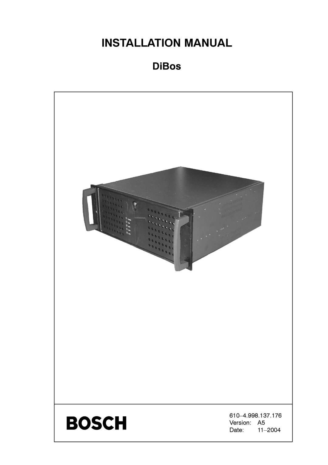
INSTALLATION MANUAL
DiBos
610–4.998.137.176
Version: A5
Date:
11–2004
Page 1
Page 2
Page 1
Image 1
Page 1
Page 2
Contents
DiBos
Installation Manual
Page
Important Safeguards
Safety instructions
FCC & Ices Information
Safety instructions
For Rack-Mount Product
For Indoor Product
Cover Removal
Risk of Electric Shock Do not Open
Safety Precautions
Table of Contents
XP Administration
Table of Contents
Configuration
Fault Indication/Correction 130 Maintenance and Service 131
Introduction
Uninterruptible Power Supply
System Description
Virus Scanners
Recommended Virus Scanners/Firewalls
Loss of individual images cannot be ruled out Firewall
System board
Introduction Component Overview
Introduction Laws/Norms/Guidelines
Guarantee
Rear view
Computer Slots
10 12
Select this function to start the Assistant
Quick installation
Logon as administrator
Existing video hardware is displayed in this dialog box
Display of the existing hardware
You can change the camera name in this dialog box
Changing the camera name
Menu Hardware/Framegrabber/Cameras
Select storage method
Quick installation
Drive is not activated
Select the drive for storage and finish Basic Configuration
610-4.998.137.176 A5/11-2004
Connections
Grabber Card MVTitan max
Grabberkarte MVTitan Pin Assignment connector J9/J11
May only be executed by authorized trained personnel
Connections Relay output
Alarm input connection
Video input termination
Pin assignment
Grabber Card MVSigma
MVSigma grabber card Video input termination
Connection to a Token Ring or Ethernet Network
Installation and configuration of the token ring card
Installation Manual for DiBos Video System
Transmitter wire
Connecting the Isdn Controller
Receiver wire
Video system
Connecting External Hard Disks
Connecting the VSCom 200 H Interface Expansion
MVTitan MVSigma Connection Connector J11 Connector J9 Ccvs
Connecting the Cameras
Cameras
Or Ccvs
Installation
Connecting the V-DOG and Tamper Contact
Connecting a Fault Indicator
Connecting the Software Dongle and the Printer
Method
Connecting the ATM via the Interface Processor Serial
Interface processor
Jumpering of OVS
Connections Method
Processor
Interface
Barcode Reader V3300-N
Connecting the Barcode Reader
Programming the V3300-N
Barcode reader DOUBLE-X-LR
Interface converter
Connecting Foyer Card Reader Miniter RS
Foyer card reader 1 Miniter RS
Foyer card Reader 4 LS23M
Connections Programming the foyer card reader Miniter RS
Connections
DCF
Connecting Radio Clock DCF
Connections
Activating/deactivating the Web application
Web Connection for Access Via Browser
Selecting and Installing the Modem
Connecting a Modem
Installing the modem
Decrease Timeout Value for Outgoing Connections
Connections
Connecting AutoDome
Connecting AutoDome/SAE-Dome
Connecting AutoDome via matrix
LTC
Connecting SAE Dome with V3032 Biphase interface
Connections Connecting SAE Dome directly
LNL-108 a SAE Dome
LTC matrix
General remarks
Connecting a Security System
Video system
Bosch SecSys
For a power supply of 230
For power supply of 12 V/24
Connections Jumper assignment for interface converter OVS
Network plug before opening the device
Connecting to BZ 500 20 mA Video system BZ 500 LSN
Connections Connecting to NZ 500 20 mA Video system
AZ 1010/NZ
MA connection to AZ 1010/NZ 1008 video system
Jumper assignment V on the SMA
MA connection to NZ 1012 video system
Dip-Fix switches S and jumpers V on SSM Interface
Connections Connecting to BZ 1012 20 mA video system
ZAN SIE ZVE
MA connection to NZ 1060 video system
Connections Connecting to BZ 1060 20 mA video system
Connecting to UEZ 2000 20 mA Video system UEZ 2000 LSN
Connections Connecting to UEZ 1000 20 mA Video system
AVM
Tesp SGK EPC/EPC2
MA connection to UGM 2020 via Uess Video system
Bosch D9000
Connections Connecting to Bosch D9000 Series video system
D9133
Changing from video system to XP administrator level
XP Administration
Log on as Windowsr XP user
May only be executed by authorized personnel
Basic configuration
Configuration
Basic configuration with the wizard
Use standard configuration program
Configuration Drives
Standard configuration expert configuration
Update
Vated drives
Archive images are evenly distributed amongst the acti
Configuration Configuration Archives
Set-up in Job macros/save
Configuration
Configuration Configuration of hardware connections
Option
Hardware/automatic teller machine menu
Time periods menu
Activate Foyer card reader time controlled
Entering lockouts
12078123456674 or
Deleting lockouts
436574 or
Configuration Configuration of barcode reader option
Installation Manual for DiBos Video System
Configuration
Installation Manual for DiBos Video System
Group .. detectors .. and click on Add
Put boxes from group ... detectors .. and to
Configuration Configuration of alarm simulation
Configuration Configuration of virtual detectors
Data types have the following format
Configuration Configuration of detector inputs
Configuration
Information regarding the Svhs cameras
Configuration Configuration of cameras
Information concerning sensor cameras
Configuration
Click on Image settings
Image settings for all camera types
Shaded
Detection. Non-sensitive areas are shown
Movement detection. Sensitive areas are shown
Not shaded
Configuration
Set dome cameras
Creating interface settings
Camera.This is how you swivel the camera
Saving camera positions
This is how you zoom
Accepting entries
Entering control commands via the command line
Configuration Configuring relays
Configuration Configuring IP cameras
Configuration
Configuration Configuring time periods
610-4.998.137.176 A5/11-2004
Options group Own user station
Configuration Configuration of the Isdn connections option
Activate Licensed remote station for projects
Configuration Configuring network connections
Configuration
Configuration Configuring modem connections
Configuration
Configuration Configuring storage job macros
Configuration
Before you begin the alarm transmission job macro
Configuration Configuring alarm transmission job macro
Configuring an alarm transmission job macro
Management/authorization levels menu
Before you begin the backup job macro
Configuration Configuring backup job macro
Select the Database/search dialog Single images menu
Configuring a backup job macro
Configuration Configuration of job activations
Configuration
610-4.998.137.176 111 A5/11-2004
Configuration Configuration of authorization levels
Outp Dome
Known to those persons responsible for this video system
Configuration Configuration of the users
610-4.998.137.176 115 A5/11-2004
Configuration Configuration of options
Configuration Configuration of security settings
Saving a unique key
Generating a unique key
Loading a unique key
Deleting a unique key
Assigning an audio signal to a connection
Configuration Configuration of audio signals
Deleting an audio signal
Loading a new dongle file
Configuration Configuration of the dongle
Deleting an existing dongle file
Figuration overwrites the current one
Configuration Administration configuration
Configuration
Startup
Switching On the PC Startup
Connecting the System Components
Activating External Hard Disks
Checking the Optional Isdn Connection
Checking the Optional Network Connection
Changing the Computer Name
Checking the Grabber Driver
H1HH
Checking the Optional ATM Connection
System Test
Checking the Optional Web Connection
Storing reference images
Log off
Fault Possible Cause Remedy
Fault Indication/Correction
Maintenance Tasks to be Carried Out
Maintenance and Service
Maintenance work to be carried out by the user
Software update
Sending a Message in the Windows Network Using net send
Error Forwarding
Sending an E-mail Using Outlook
Testing Error Forwarding
Maintenance and Service Sending an SMS
Troubleshooting
Video System in 19 Housing
Technical data
Grabber card MVSigma
Technical Data Grabber card MVTitan
End user license agreement Eula
End user license agreement
Page
Top
Page
Image
Contents