Installation Manual for DiBos Video System
Connections (continued)
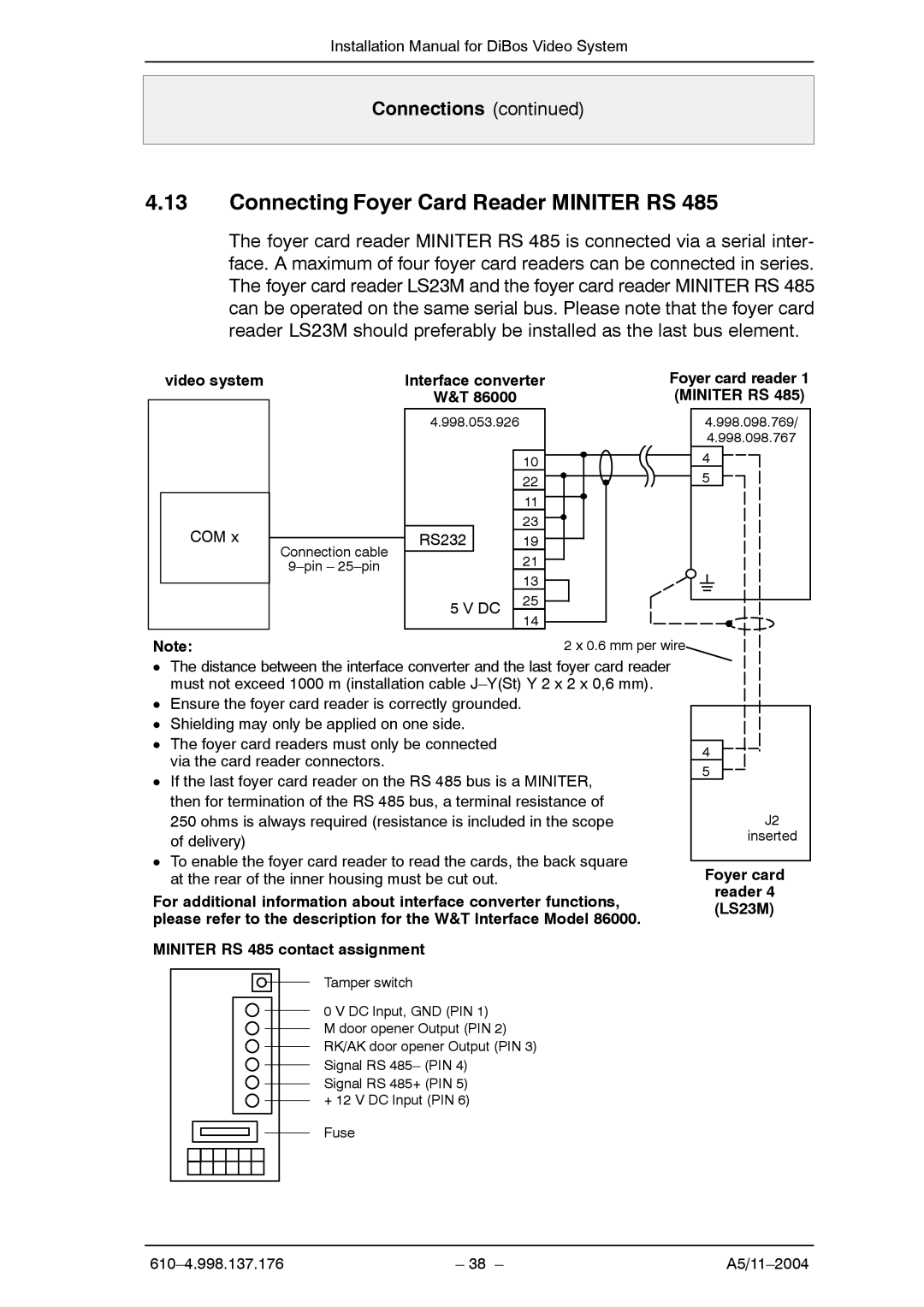
4.13Connecting Foyer Card Reader MINITER RS 485
The foyer card reader MINITER RS 485 is connected via a serial inter- face. A maximum of four foyer card readers can be connected in series. The foyer card reader LS23M and the foyer card reader MINITER RS 485 can be operated on the same serial bus. Please note that the foyer card reader LS23M should preferably be installed as the last bus element.
video system
COM x
Connection cable
Interface converter
W&T 86000
4.998.053.926
|
| 10 | |
|
| 22 | |
|
| 11 | |
|
| 23 | |
RS232 |
| 19 | |
|
| 21 | |
|
| 13 | |
5 V DC | 25 | ||
14 | |||
|
| ||
Foyer card reader 1 (MINITER RS 485)
4.998.098.769/
4.998.098.767
4
5
Note: | 2 x 0.6 mm per wire |
DThe distance between the interface converter and the last foyer card reader must not exceed 1000 m (installation cable
DEnsure the foyer card reader is correctly grounded.
DShielding may only be applied on one side.
DThe foyer card readers must only be connected via the card reader connectors.
DIf the last foyer card reader on the RS 485 bus is a MINITER, then for termination of the RS 485 bus, a terminal resistance of 250 ohms is always required (resistance is included in the scope of delivery)
DTo enable the foyer card reader to read the cards, the back square at the rear of the inner housing must be cut out.
For additional information about interface converter functions, please refer to the description for the W&T Interface Model 86000.
MINITER RS 485 contact assignment
4
5
J2
inserted
Foyer card
reader 4 (LS23M)
Tamper switch
0 V DC Input, GND (PIN 1) M door opener Output (PIN 2) RK/AK door opener Output (PIN 3) Signal RS 485– (PIN 4)
Signal RS 485+ (PIN 5)
+12 V DC Input (PIN 6) Fuse
| – 38 – |