Installation Manual for DiBos Video System
Configuration (continued)
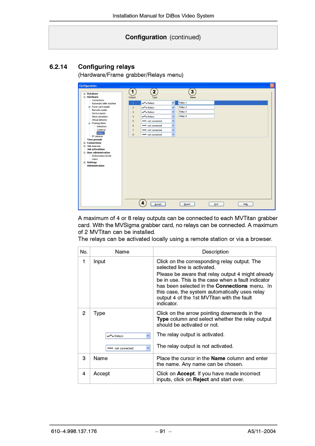
6.2.14Configuring relays
(Hardware/Frame grabber/Relays menu)
A maximum of 4 or 8 relay outputs can be connected to each MVTitan grabber card. With the MVSigma grabber card, no relays can be connected. A maximum of 2 MVTitan can be installed.
The relays can be activated locally using a remote station or via a browser.
No. | Name | Description |
|
|
|
1 | Input | Click on the corresponding relay output. The |
|
| selected line is activated. |
|
| Please be aware that relay output 4 might already |
|
| be in use. This is the case when a fault indicator |
|
| has been selected in the Connections menu. In |
|
| this case, the system automatically uses relay |
|
| output 4 of the 1st MVTitan with the fault |
|
| indicator. |
|
|
|
2 | Type | Click on the arrow pointing downwards in the |
|
| Type column and select whether the relay output |
|
| should be activated or not. |
|
| The relay output is activated. |
|
| The relay output is not activated. |
|
|
|
3 | Name | Place the cursor in the Name column and enter |
|
| the name. Any name can be chosen. |
|
|
|
4 | Accept | Click on Accept. If you have made incorrect |
|
| inputs, click on Reject and start over. |
|
|
|
– 91 – |