Power MOSFET Switching Waveforms:
A New Insight
| Application Note | October 1999 | |
|
|
|
|
|
|
|
|
Title N75
The examination of power MOSFET voltage and current waveforms during switching transitions reveals that the device characterization now practiced by industry is inade- quate. In this Note, device waveforms are explained by con- sidering the interaction of a vertical JFET driven in cascode
SOURCE METAL
POLY GATE GLASS GATE OXIDE
)
ub- t ower OS-
T
from a lateral MOSFET in combination with the interelec- trode capacitances. Particular attention is given to the
n+ SOURCE ![]()
![]()
![]()
![]()
MOS
pBODY
p+ ![]()
JFET |
|
|
| 0 | |
|
|
| 10 VOLTS | |
|
|
| ||
|
|
| ||
|
|
| ||
n- |
|
| DEPLETION EDGE | |
| ||||
|
|
| 40 VOLTS | |
|
|
| ||
n+ DRAIN | ||||
| ||||
witch g ave- rms: New si t) utho
)
ey- ords ter-
rpo- ion, mi- n- ctor) re- or ()
OCI
FO f- ark
age- ode se- ut- es
to observed waveforms. The nature of the “asymmetric switching times” is explained.
A waveform family is proposed as a more descriptive and accurate method of characterization. This new format is a plot of drain voltage and gate voltage versus normalized time. A family of curves is presented for a constant load resistance with VDS varied. Gate drive during switching transitions is a constant current with voltage compliance limits of 0 and 10 volts. Time is normalized by the value of gate driving current. The normalization shows excellent agreement with data over five orders of magnitude, and is bounded on one extreme by gate propagation effects and on the other by transition time
Device Models
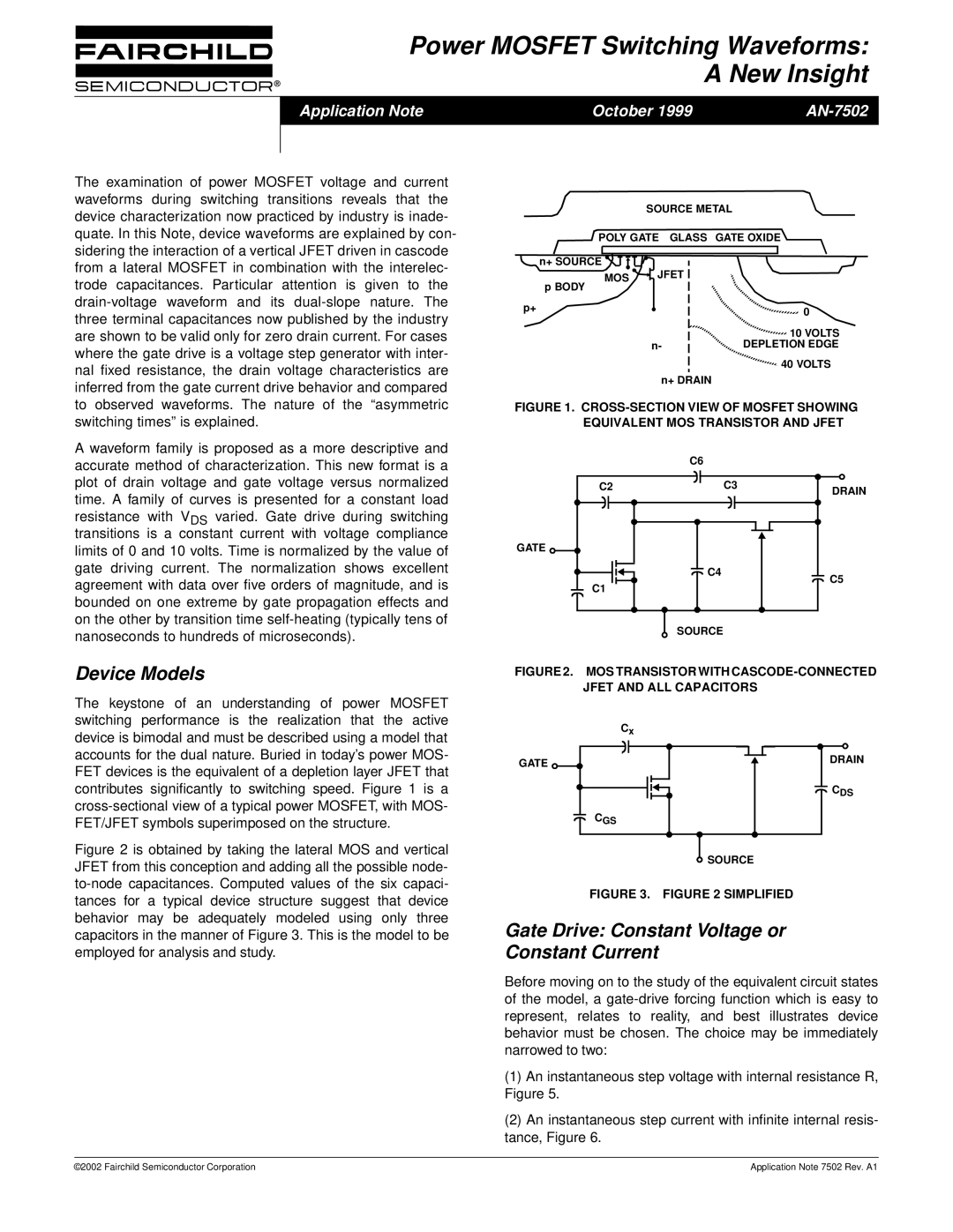
The keystone of an understanding of power MOSFET switching performance is the realization that the active device is bimodal and must be described using a model that accounts for the dual nature. Buried in today’s power MOS- FET devices is the equivalent of a depletion layer JFET that contributes significantly to switching speed. Figure 1 is a
Figure 2 is obtained by taking the lateral MOS and vertical JFET from this conception and adding all the possible node- to-node capacitances. Computed values of the six capaci- tances for a typical device structure suggest that device behavior may be adequately modeled using only three capacitors in the manner of Figure 3. This is the model to be employed for analysis and study.
FIGURE 1. CROSS-SECTION VIEW OF MOSFET SHOWING EQUIVALENT MOS TRANSISTOR AND JFET
| C6 |
|
C2 | C3 | DRAIN |
|
| |
GATE |
|
|
| C4 | C5 |
C1 |
| |
|
| |
| SOURCE |
|
FIGURE 2. MOS TRANSISTOR WITH CASCODE-CONNECTED JFET AND ALL CAPACITORS
| Cx |
GATE | DRAIN |
| |
| CDS |
| CGS |
![]() SOURCE
SOURCE
FIGURE 3. FIGURE 2 SIMPLIFIED
Gate Drive: Constant Voltage or Constant Current
Before moving on to the study of the equivalent circuit states of the model, a
(1)An instantaneous step voltage with internal resistance R, Figure 5.
(2)An instantaneous step current with infinite internal resis- tance, Figure 6.
©2002 Fairchild Semiconductor Corporation | Application Note 7502 Rev. A1 |