Application Note 7502
State 1: MOS Off, JFET Off
State 5: Mos Active, JFET Saturated
The JFET current generator VxgmJ, is operative.
IPK1 = VG/RO
State 2: MOS Active, JFET Active
IPK2 = (VG - VGS(TH))/RO
t =
[VDK - VD[SAT])CX
IPK5
State 3: MOS Active, JFET Saturated
IPK3 = (VG - VG(SAT))/RO
Turn-Off
IPK5 = VG(SAT)/RO
State 6: Mos Active, JFET Active
The Miller effect is now reduced by the activation of VGgMJ, and the equivalent circuit predicts:
State 4: MOS Saturated, JFET Saturated
IPK4 = VG/RO
t =
[VDD - VDK][CGS + CX(1 + gM/gMJ)]
gMRL IPAK6
State 5: MOS Active, JFET Saturated
IPK5 = VG(SAT)/RO
State 6: MOS Active, JFET Active
IPK6 = VG(SAT)/RO
The equivalent circuit of Figure
where T1 = ROCGS + (1 + gM/gMJ)ROCX
IPAK6 = VG(SAT)/RO
Appendix B - Estimating RO for Some Typical
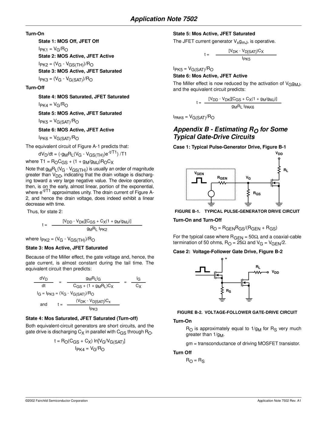
Case 1: Typical Pulse-Generator Drive, Figure B-1
VDD
Note that gMRL(VG - VGS(TH)) is usually an order of magnitude greater than VDD, indicating that the drain voltage is discharg-
VGEN
RL
ing toward a very large negative value. The device operation, then, is on the early, almost linear, portion of the exponential, where
Thus, for state 2:
RGEN | VG |
RGS
FIGURE B-1. TYPICAL PULSE-GENERATOR DRIVE CIRCUIT
t =
[VDD - VDK][CGS + CX(1 + gM/gMJ)]
gMRL IPK2
Turn-On and Turn-Off
RO = RGENRGS/(RGEN + RGS)
where IPK2 = (VG - VGS(TH))/RO
State 3: Mos Active, JFET Saturated
Because of the Miller effect, the gate voltage and, hence, the gate current, is almost constant during the tail time. The equivalent circuit then predicts:
dVD | = | gMRLlG | = | lG | |
dt | CGS + (1 + gMRL)CX | CX | |||
|
| ||||
lG = IPK3 = (VG - VG(SAT))/RO |
|
| |||
and | t = | (VDK - VD[SAT])Cx |
|
| |
|
|
| |||
IPK3
State 4: Mos Saturated, JFET Saturated (Turn-off)
Both
t= RO(CGS + CX) ln[VG/VG(SAT)] IPK4 = VG/RO
For the typical case where RGEN = 50Ω, and a
Case 2: Voltage-Follower Gate Drive, Figure B-2
![]() +
+
RL
VDD
RS
FIGURE B-2. VOLTAGE-FOLLOWER GATE-DRIVE CIRCUIT
Turn-On
RO is approximately equal to 1/gM for RS very much greater than 1/gM.
gm = transconductance of driving MOSFET transistor.
Turn Off
RO = RS
©2002 Fairchild Semiconductor Corporation | Application Note 7502 Rev. A1 |