Manuals
/
Falcon
/
Home Audio
/
Stereo System
Falcon
15
manual
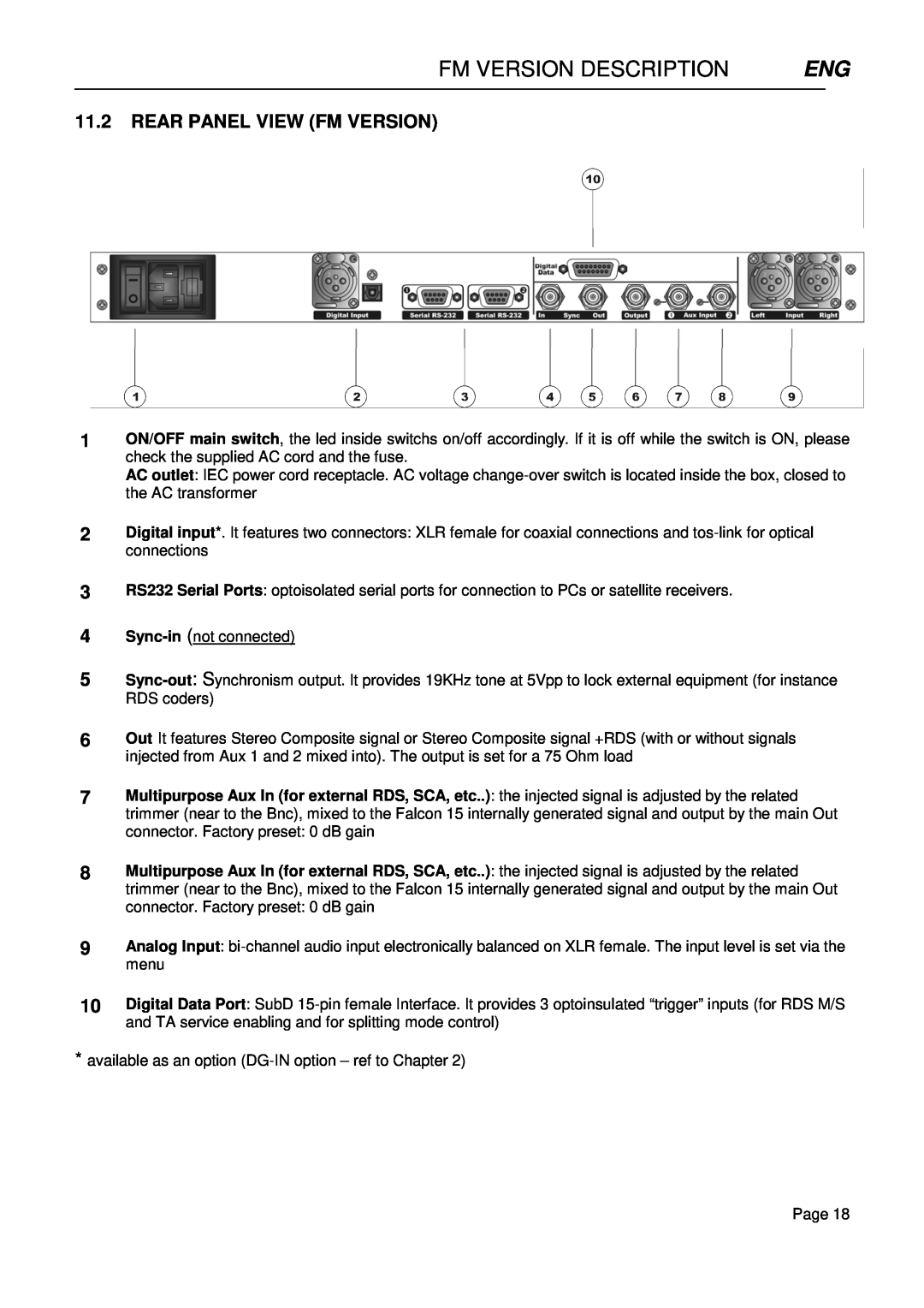
Fm Version Description, 11.2REAR PANEL VIEW FM VERSION
Models:
15
1
18
74
74
Download
74 pages
58.11 Kb
15
16
17
18
19
20
21
22
Specification
Block Diagram Fm
Warranty
15.2THE FALCON 15 PRESET TABLE
Serial Port Setup
11.4OUTPUT CONNECTOR
In & Out Settings Fm Version
9.3FUSE REPLACEMENT
Safety
18.6PROGRAM SERVICE NAME PS
Page 18
Image 18
Page 17
Page 19
Page 18
Image 18
Page 17
Page 19
Contents
Operating manual
Falcon
FM & ST
Broadcast Digital Audio Processor
Page
1 TABLE OF CONTENTS
TABLE OF CONTENTS
TABLE OF CONTENTS
13 ST VERSION DESCRIPTION
TABLE OF CONTENTS
HARDWARE SETTINGS
2 INTRODUCTION
INTRODUCTION ENG
Falcon 15 ST
INTRODUCTION ENG
2.1FALCON 15 - AVAILABLE VERSIONS
Falcon 15 FM
SAFETY WARNINGS CONSIGNES DE SÉCURITÉ IMPORTANTES
3 SAFETY WARNINGS / ISTRUZIONI PER LA SICUREZZA
SAFETY WARNINGS / ISTRUZIONI PER LA SICUREZZA
ISTRUZIONI IMPORTANTI PER LA SICUREZZA
4 SAFETY WARNINGS
SAFETY WARNINGS
5 CONSIGNES DE SÉCURITÉ IMPORTANTES
CONSIGNES DE SÉCURITÉ IMPORTANTES
6 ISTRUZIONI IMPORTANTI PER LA SICUREZZA
ISTRUZIONI IMPORTANTI PER LA SICUREZZA
7 WICHTIGE SICHERHEITSHINWEISE
WICHTIGE SICHERHEITSHINWEISE
8 INSTRUCCIONES IMPORTANTES DE SEGURIDAD
INSTRUCCIONES IMPORTANTES DE SEGURIDAD
Manufacturer
9 FIRST INSTALLATION RECOMMENDATIONS
FIRST INSTALLATION RECOMMENDATIONS
Model
FIRST INSTALLATION RECOMMENDATIONS
9.3FUSE REPLACEMENT
BLOCK DIAGRAM FM
VERSIONSDIAGRAM FM & ST
ST VERSIONS
digital coder MPX+RDS
11 FM VERSION DESCRIPTION
FM VERSION DESCRIPTION
FM VERSION DESCRIPTION
11.2REAR PANEL VIEW FM VERSION
FM VERSION DESCRIPTION
11.4OUTPUT CONNECTOR
11.5SYNC-INAND SYNC-OUTCONNECTORS
11.3AC CONNECTION
FM VERSION DESCRIPTION
11.6AUXILIARY INPUTS
11.7ANALOG AUDIO INPUT Female XLR
FM VERSION DESCRIPTION
11.8DIGITAL AUDIO INPUT
11.9SERIAL PORTS
DESCRIPTION
FM VERSION DESCRIPTION
11.10 DIGITAL DATA PORT
DIRECTION
FM VERSION DESCRIPTION
Page
FM VERSION DESCRIPTION
11.11 THE MENU TREE
FM VERSION DESCRIPTION
11.12 FRONT PANEL OPERATION
12.1.2ADJUSTING THE INPUT AUDIO LEVEL
12 IN & OUT SETTINGS FM VERSION
IN & OUT SETTINGS FM VERSION
12.1.1 SELECTING THE INPUT ANALOG OR DIGITAL
IN & OUT SETTINGS FM VERSION
12.1.3 CHOOSING THE PROPER AGC OPERATION
IN & OUT SETTINGS FM VERSION
12.2THE VOICE OPTIMIZER
Page
12.3.3 ADJUSTING THE MPX OUTPUT LEVEL
IN & OUT SETTINGS FM VERSION
12.3.1 SETTING THE PREEMPHASIS
12.3.2 MONO - STEREO OPERATION
12.3.5 ENABLING SYNC OUTPUT
IN & OUT SETTINGS FM VERSION
12.3.4 CALIBRATING THE PILOT LEVEL AND PHASE
2Select the Peak Reference Tone option
IN & OUT SETTINGS FM VERSION
12.3.6NOISE GATE SETTING Noise Gate
12.3.7 BYPASS MODE
IN & OUT SETTINGS FM VERSION
31.5dB
D=2.0 KHz
IN & OUT SETTINGS FM VERSION
12.5SETTING THE SPLIT MODES
12.6.1 SERIAL PORT SETUP
IN & OUT SETTINGS FM VERSION
12.6ADDITIONAL DATA AND SETTINGS
12.6.2 SYSTEM INFO
13 ST VERSION DESCRIPTION
ST VERSION DESCRIPTION
ST VERSION DESCRIPTION
13.2REAR PANEL VIEW ST VERSION
ST VERSION DESCRIPTION
13.3AC CONNECTION
13.4DIGITAL AUDIO INPUT
ST VERSION DESCRIPTION
13.5SERIAL PORTS
13.6ANALOG AUDIO OUTPUT Male XLR
ST VERSION DESCRIPTION
13.7ANALOG AUDIO INPUT Female XLR
ST VERSION DESCRIPTION
13.8FALCON 15 MENU TREE ST version
ST VERSION DESCRIPTION
13.9FRONT PANEL OPERATION
14.1.2ADJUSTING THE INPUT AUDIO LEVEL
14 IN / OUT SETTINGS ST version
IN / OUT SETTINGS ST version
14.1.1 SELECTING THE INPUT ANALOG OR DIGITAL
IN / OUT SETTINGS ST version
14.1.3 CHOOSING THE PROPER AGC OPERATION
IN / OUT SETTINGS ST version
14.2THE VOICE OPTIMIZER
IN / OUT SETTINGS ST version
14.3.1 SETTING THE PREEMPHASIS
14.3.3 BYPASS MODE
IN / OUT SETTINGS ST version
14.3.2 ADJUSTING THE AUDIO OUTPUT LEVEL
2Select the Peak Reference Tone option
IN / OUT SETTINGS ST version
14.3.5NOISE GATE SETTING Noise Gate
14.3.4 MONO - STEREO OPERATION
14.4.1 SERIAL PORT SETUP
IN / OUT SETTINGS ST version
14.4ADDITIONAL DATA AND SETTINGS
14.4.2 SYSTEM INFO
15 CHOOSING THE PROCESSING CURVE
CHOOSING THE PROCESSING CURVE
15.2THE FALCON 15 PRESET TABLE
CHOOSING THE PROCESSING CURVE
CHOOSING THE PROCESSING CURVE
15.3CHOOSING A CURVE
16 THE REMOTE PC CONTROL SOFTWARE
THE REMOTE PC CONTROL SOFTWARE
THE REMOTE PC CONTROL SOFTWARE
16.3RUNNING THE PROGRAM
16.4PC CONTROL SOFTWARE OVERVIEW
17 ACCESSING THE TARGET FROM THE PC
ACCESSING THE TARGET FROM THE PC
ACCESSING THE TARGET FROM THE PC
17.1THE SETUP PANEL
17.1.1 SELECTING THE PC SERIAL PORT
ACCESSING THE TARGET FROM THE PC
17.1.2 OTHER SETTINGS
17.1.3 FRONT PANEL ‘LOCK’ FUNCTION
18 RDS / RBDS SETTINGS FM Version only
RDS / RBDS SETTINGS FM Version only
RDS / RBDS SETTINGS FM Version only
18.3CHANGING THE RDS / RBDS OUTPUT LEVEL
RDS / RBDS SETTINGS FM Version only
Page
RDS / RBDS SETTINGS FM Version only
18.5.1 RDS / RBDS SERVICES DESCRIBED
18.6.2 THE PROGRAM SERVICE NAME EDITOR
RDS / RBDS SETTINGS FM Version only
18.6PROGRAM SERVICE NAME PS
18.6.1 SCOPE
RDS / RBDS SETTINGS FM Version only
18.6.3 PS SEQUENCES
Max lenght 32 characters
RDS / RBDS SETTINGS FM Version only
18.6.4PS SCROLLING
Page
RDS / RBDS SETTINGS FM Version only
18.7ALTERNATIVE FREQUENCIES
RDS / RBDS SETTINGS FM Version only
18.8AF METHODS A AND B
METHOD A
RDS / RBDS SETTINGS FM Version only
METHOD B
RDS / RBDS SETTINGS FM Version only
Page
19 HARDWARE SETTINGS
HARDWARE SETTINGS
20 FIRMWARE E SOFTWARE UPGRADES
FIRMWARE E SOFTWARE UPGRADES
1MAKING THE PROCESSOR READY FOR UPGRADING
FIRMWARE E SOFTWARE UPGRADES
2 PC OPERATION
FIRMWARE E SOFTWARE UPGRADES
20.2PC SOFTWARE UPGRADE
GENERAL FEATURES
21 TECHNICAL SPECIFICATIONS
TECHNICAL SPECIFICATIONS
REMOTE CONTROL
22 WARRANTY
WARRANTY ENG
RDS / RBDS CODER FM version only
23 WEEE Directive - Informativa RAEE
WEEE Directive - Informativa RAEE
Top
Page
Image
Contents