User Guide
Contents
Ventilation
Installation and Maintenance
Personal Safety
Before You Start
do not use the hob surface as a cutting board
Cleaning
Hob Care
Cooker Care
Hob
Cooker Overview
Automatic Heat-up, a
Residual Heat Indicator, H
Pan Detector
0Fig.2-8
Glide-out Grill
Child Lock, L
Pan Protection Function
Multi-function oven functions
Never close the grill door when the grill is on
Ovens
Left-Hand Multi-function Oven
Conventional oven top and base heat
Fan oven
Fanned grilling
Fan assisted oven
Operating the Ovens
Right-hand tall oven
Minute Minder
Setting the time of day
To start and then stop the left-hand oven using the Timer
Clock
Oven Shelves Left-hand Main Oven
Accessories
Auto is showing, but you want to revert to manual cooking
Key Lock
Handyrack Main Oven
Main Oven Light
Oven shelves Right-hand Tall Oven
General Oven Tips
Tips on Cooking with the Timer
Cooking Tips
Daily Care
Cleaning Your Cooker
Cleaning Spills
Cleaning Burned-on Spills
Control Panel and Doors
‘Cook & Clean’ Panels
Tall Oven
Removing the Panels to clean the Enamel Interior
Troubleshooting
Food is cooking too slowly, too quickly, or burning
Timed oven is not coming on when turned on manually
Timed oven is not coming on when automatic cooking
Oven temperature getting hotter as the cooker gets older
Provision of Ventilation
Installation
Dear Installer
Safety Requirements
Moving the Cooker
Positioning the Cooker
Unpacking the Cooker
Fitting the Handles
Completing the Move
Repositioning the Cooker following Connection
Levelling
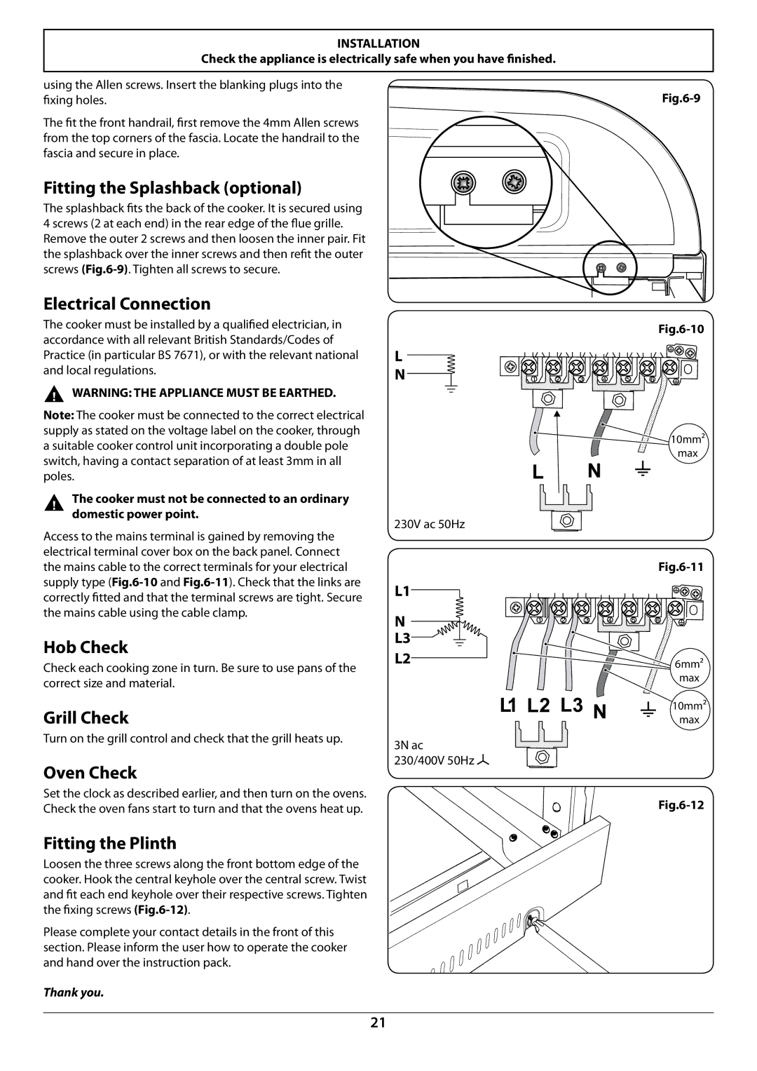
Grill Check
Fitting the Splashback optional
Electrical Connection
Hob Check
Servicing
The door is heavy, so take care
To Adjust an Oven Door Angle
To Remove Grill Element
To Replace an Oven Door
To Replace an Oven Door Seal
To Adjust the Main Oven Door Catch Keep
To Replace the Tall Oven Door Outer Panel
To Change the Main Oven Door Latch
To Change Oven Light Bulb
To Replace an Oven Fan
To Remove the Left-hand Oven Bottom and Top Elements
Code Description Colour Code
Circuit Diagram Oven
Key
Circuit Diagram Hob
Connections
Technical Data
Dimensions
Français
Sécurité personnelle
Installation et Entretien
Avant de commencer…
Odeur de neuf
Nettoyage
Français Conseils relatifs à la table de cuisson
Table de cuisson
Vue d’ensemble de la Cuisinière
Tableau
Détection de récipient de cuisson
Indicateur de chaleur résiduelle, H
Protection de récipient de cuisson
Chauffage automatique, a
Verrouillage sécurité enfants, L
Fonctions du four multifonctions
Gril Coulissant Glide-out
Fours
Four gauche
Four ventilé mixte
Four ventilé
Gril ventilé
Fonctionnement des fours
Four droit
Arrêt automatique du four gauche
Horloge
Réglage de l’heure
Minuterie
Désactivation de la fonction de verrouillage
Fonction de verrouillage
Grilles de four Four gauche four principal
Activation de la fonction de verrouillage
Handyrack
Eclairage du Four
Grilles de four Four droit four haut
Conseils généraux pour la cuisson au four
Conseils pour la Cuisson
Nettoyage des Déversements Accidentels
Nettoyage de la Cuisinière
Informations importantes
Entretien Quotidien
Nettoyage des Déversements Brûlés
Gril Coulissant
Panneaux autonettoyants
Panneau de Commande et Portes
Four Haut
Dépannage
’éclairage du four ne fonctionne pas
La cuisson au four n’est pas uniforme
Le four ne s’allume pas
Positionnement de la Cuisinière
’intention de l’installateur
Emplacement de la Cuisinière
Prescriptions de Sécurité
Déballage de la Cuisinière
Déplacement de la Cuisinière
Mise à Niveau
Abaissement des Deux Galets Arrière
Positionnement Final
Repositionnement de la Cuisinière après Raccordement
Contrôle du gril
Montage des poignées
Raccordement Électrique
Contrôle de la Table de Cuisson
Entretien
Remplacement d’un élément de table de cuisson
Remplacement d’une porte de four
Remplacement de l’interrupteur d’éclairage
Remplacement d’un thermostat
Remplacement d’un regulateur de gril
19. Dépose d’un protecteur thermique d’element de four
Remplacement du verrouillage de porte principale de four
Remplacement d’un joint de porte de four
22. Dépose du ventilateur du four
Remplacement de l’ampoule d’éclairage du four
20. Dépose de la partie arriere interne du four
21. Dépose de l’element du four ventile
Code Elément Couleur
Schéma de câblage Fours
Légende
Schéma de câblage Table de cuisson
Electricité
Fiche technique
Raccordments
Puissances
ArtNo.000-0001 Aga address block