Manuals
/
Fender
/
Kitchen Appliance
/
Mixer
Fender
SRM 8302, SRM 6302
manual
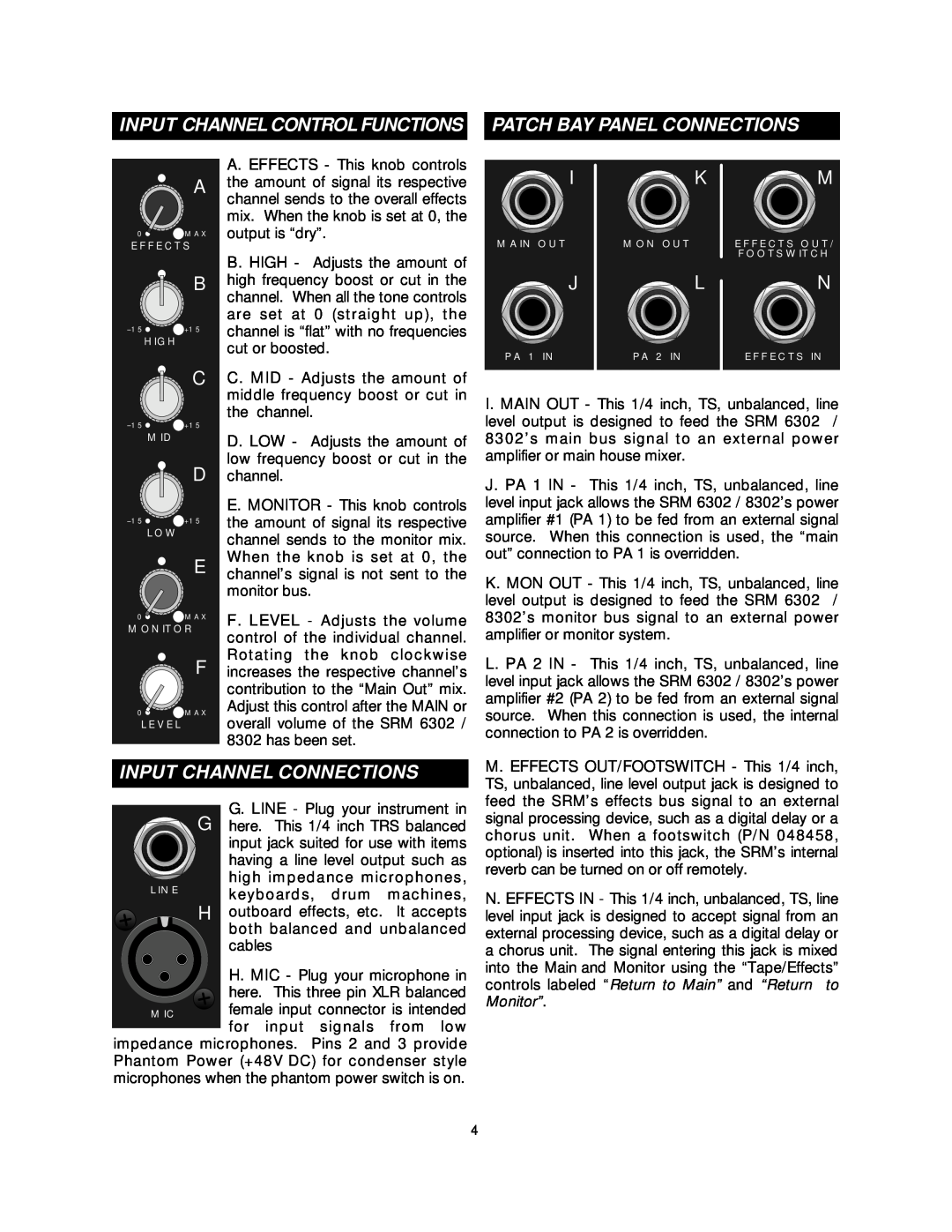
Input Channel Connections
Models:
SRM 6302
SRM 8302
1
4
16
16
Download
16 pages
38.99 Kb
1
2
3
4
5
6
7
8
Troubleshooting
Specs
Typical signal path
BASIC SETUP OF YOUR SRM 6302
Powered Mixers
Page 4
Image 4
Page 3
Page 5
Page 4
Image 4
Page 3
Page 5
Contents
POWERED MIXERS
From Fender Pro Audio
Bill Schultz
Fender Musical Instruments
INTRODUCTION
PROFESSIONAL POWERED MIXER
Assignable Dual Power Amplifiers
+48V DC Phantom Power
INPUT CHANNEL CONNECTIONS
MASTER CONTROL PANEL FUNCTIONS
Phantom Power supply is off
Before
plugging or unplugging any
REAR PANEL
TAPE INPUT / OUTPUT JACKS
tape/effects return to main and
100-UP
INPUT / OUTPUT CONNECTIONS
BASIC SETUP OF YOUR SRM 6302 /
GROUNDING AND HUMS
TROUBLESHOOTING
TOLEX COVERING CARE
SIMPLE SRM SETUP WITH MONITORS
RUNNING AN EFFECTS PROCESSOR THRU YOUR SRM
Page
1.Connect a cord from the Main Out jack to an external power amp. Be sure one monitor enclosure is connected to a PA 1 Out jack and the other is connected to a PA 2 Out jack. PA 1 power amp can now be assigned to monitor speakers by connecting a small, shielded jumper cable from the Mon Out jack to PA 1 In. Next, connect the PA2 power amp to Monitor Out by placing the PA2 Assign switch to the Mon position. The Monitor control will now adjust volume for both PA 1 and PA
Typical signal path
SRM 6302 / 8302 SIGNAL FLOW DIAGRAM
for each channel
SPECIFICATIONS FOR THE SRM
SPECIFICATIONS FOR THE SRM
DESIGNATION TYPE
Top
Page
Image
Contents