MASTER CONTROL PANEL FUNCTIONS
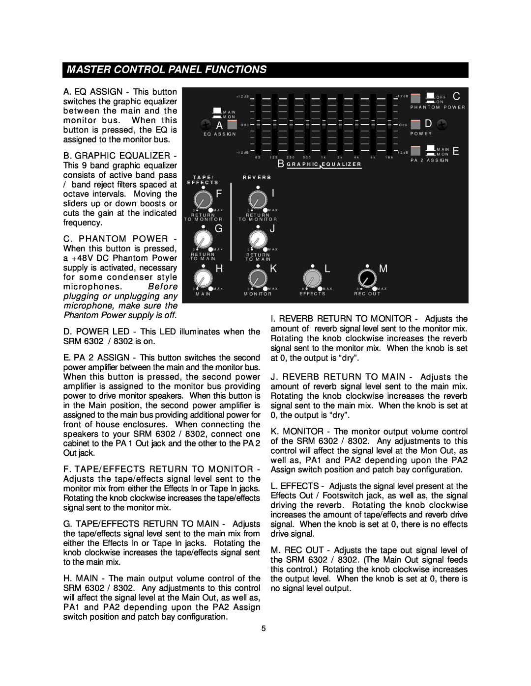
A. EQ ASSIGN - This button switches the graphic equalizer between the main and the monitor bus. When this button is pressed, the EQ is assigned to the monitor bus.
+12dB
![]() MAIN
MAIN
![]() MON
MON
A OdB
EQ ASSIGN
+12dB | OFF | C |
|
![]() ON
ON
PHANTOM POWER
OdB D
POWER
|
|
|
| 12dB |
|
|
|
|
|
| 12dB | MAIN | |
B. GRAPHIC EQUALIZER - |
|
| 125 | 250 500 | 1k | 2k | 4k | 8k | MON E | ||||
|
| 63 | 16k | ||||||||||
|
|
|
|
|
|
|
|
|
|
|
| ||
This 9 band graphic equalizer |
|
|
| B GRAPHIC EQUALIZER |
| PA 2 ASSIGN | |||||||
|
|
|
|
|
| ||||||||
consists of active band pass | TAPE/ | REVERB |
|
|
|
|
|
|
| ||||
/ band reject filters spaced at | EFFECTS |
| I |
|
|
|
|
|
|
| |||
octave intervals. | Moving the |
| F |
|
|
|
|
|
|
|
| ||
sliders up or down boosts or |
|
|
|
|
|
|
|
|
|
|
| ||
cuts the gain at the indicated | 0 | MAX | 0 | MAX |
|
|
|
|
|
|
| ||
RETURN | RETURN |
|
|
|
|
|
|
| |||||
frequency. |
| TO MONITOR | TO MONITOR |
|
|
|
|
|
|
| |||
|
| G |
| J |
|
|
|
|
|
|
| ||
C. PHANTOM POWER - |
|
|
|
|
|
|
|
|
| ||||
|
|
|
|
|
|
|
|
|
|
| |||
When this button is pressed, | 0 | MAX | 0 | MAX |
|
|
|
|
|
|
| ||
a +48V DC Phantom Power | RETURN | RETURN |
|
|
|
|
|
|
| ||||
TO MAIN | TO MAIN |
|
|
|
|
|
|
| |||||
supply is activated, necessary |
| H |
| K |
| L |
|
| M |
| |||
for some condenser style |
|
|
|
|
|
|
|
|
|
|
| ||
microphones. | Before | 0 | MAX | 0 | MAX | 0 | MAX | 0 |
| MAX |
| ||
plugging or unplugging any |
| MAIN | MONITOR | EFFECTS |
| REC OUT |
| ||||||
|
|
|
|
|
|
|
|
|
|
| |||
microphone, make sure the |
|
|
|
|
|
|
|
|
|
|
| ||
Phantom Power supply is off. |
|
|
| I. REVERB RETURN TO MONITOR - | Adjusts the | ||||||||
|
|
|
|
| |||||||||
D. POWER LED - This LED illuminates when the | amount of reverb signal level sent to the monitor mix. | ||||||||||||
Rotating the knob clockwise increases the reverb | |||||||||||||
SRM 6302 / 8302 is on. |
|
|
| ||||||||||
|
|
| signal sent to the monitor mix. When the knob is set | ||||||||||
E. PA 2 ASSIGN - This button switches the second | |||||||||||||
at 0, the output is “dry”. |
|
|
| ||||||||||
power amplifier between the main and the monitor bus. |
|
|
|
|
|
|
|
| |||||
When this button is pressed, the second power | J. REVERB RETURN TO MAIN - | Adjusts the | |||||||||||
amplifier is assigned to the monitor bus providing | amount of reverb signal level sent to the main mix. | ||||||||||||
power to drive monitor speakers. When this button is | Rotating the knob clockwise increases the reverb | ||||||||||||
in the Main position, the second power amplifier is | signal sent to the main mix. When the knob is set at | ||||||||||||
assigned to the main bus providing additional power for | 0, the output is “dry”. |
|
|
|
| ||||||||
front of house enclosures. When connecting the | K. MONITOR - The monitor output volume control | ||||||||||||
speakers to your SRM 6302 / 8302, connect one | |||||||||||||
cabinet to the PA 1 Out jack and the other to the PA 2 | of the SRM 6302 / 8302. |
| Any adjustments to this | ||||||||||
Out jack. |
|
|
|
| control will affect the signal level at the Mon Out, as | ||||||||
F. TAPE/EFFECTS RETURN TO MONITOR - | well as, PA1 and PA2 depending upon the PA2 | ||||||||||||
Assign switch position and patch bay configuration. | |||||||||||||
Adjusts the tape/effects signal level sent to the | L. EFFECTS - | Adjusts the signal level present at the | |||||||||||
monitor mix from either the Effects In or Tape In jacks. | |||||||||||||
Rotating the knob clockwise increases the tape/effects | Effects Out / Footswitch jack, as well as, the signal | ||||||||||||
signal sent to the monitor mix. |
|
|
| driving the reverb. | Rotating the knob clockwise | ||||||||
G. TAPE/EFFECTS RETURN TO MAIN - | Adjusts | increases the amount of tape/effects and reverb drive | |||||||||||
signal. When the knob is set at 0, there is no effects | |||||||||||||
the tape/effects signal level sent to the main mix from | drive signal. |
|
|
|
|
|
| ||||||
either the Effects In or Tape In jacks. Rotating the | M. REC OUT - Adjusts the tape out signal level of | ||||||||||||
knob clockwise increases the tape/effects signal sent | |||||||||||||
to the main mix. |
|
|
|
| the SRM 6302 / 8302. (The Main Out signal feeds | ||||||||
H. MAIN - The main output volume control of the | this control.) | Rotating the knob clockwise increases | |||||||||||
the output level. When the knob is set at 0, there is | |||||||||||||
SRM 6302 / 8302. Any adjustments to this control | no signal level output. |
|
|
|
| ||||||||
will affect the signal level at the Main Out, as well as, |
|
|
|
|
|
|
|
| |||||
PA1 and PA2 depending upon the PA2 Assign |
|
|
|
|
|
|
|
| |||||
switch position and patch bay configuration. |
|
|
|
|
|
|
|
|
| ||||
5