SPEAKER WIRING AND CONNECTIONS
Parallel or series are the two basic ways which multiple speakers can be connected to a single power amplifier. When speakers are connected in parallel, their combined impedance decreases. For speakers wired in series the opposite is true, their combined impedance increases. Also, when speakers are wired in series, higher impedance speakers in the series draw more power from the amplifier than do speakers in the series with lower impedances. When speakers are wired in parallel, the opposite is true.
At Fender®, we recommend connecting multiple speakers in parallel for several reasons. First, if one speaker fails, the others will continue to operate. Second, because in a series connection one speaker affects the output of the other speakers, unpredictable frequency response is a concern. Third, most speaker cabinets are already wired for
Additionally, power and audio signal cables are the most common sources of sound system failure. Well made and carefully maintained cables are essential to the reliability of the entire sound system. If long speaker cables are required, it is important to ensure the cable is sufficient to transfer all of the available amplifier power to the speakers rather than absorbing the power itself. As a rule of thumb, larger wires are better as they conduct more power to the speakers (larger wire has smaller gauge numbers).
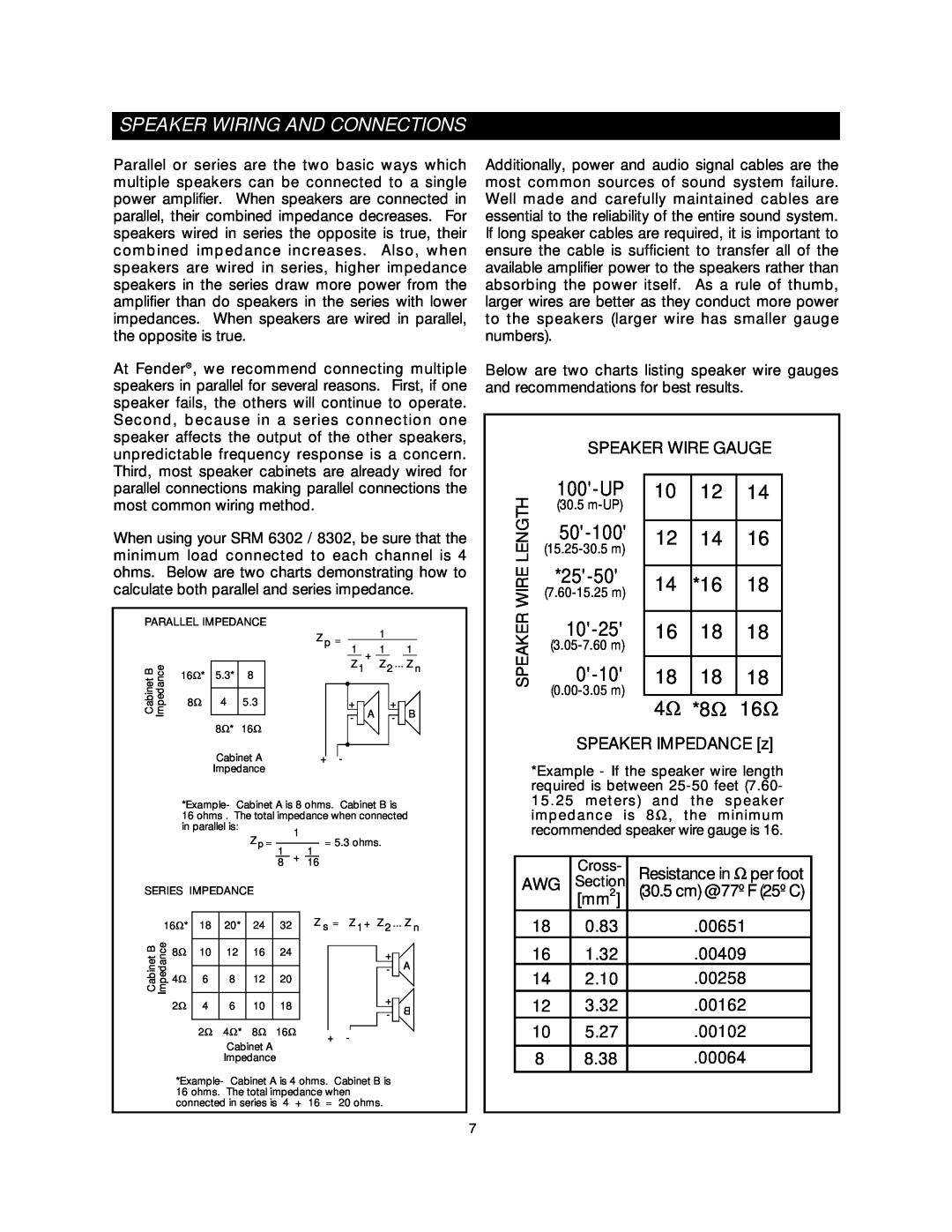
Below are two charts listing speaker wire gauges and recommendations for best results.
SPEAKER WIRE GAUGE
parallel connections making parallel connections the most common wiring method.
When using your SRM 6302 / 8302, be sure that the minimum load connected to each channel is 4 ohms. Below are two charts demonstrating how to calculate both parallel and series impedance.
PARALLEL IMPEDANCE |
|
| 1 |
|
| ||||
|
|
|
|
| Z p = |
|
|
| |
|
|
|
|
|
|
|
|
| |
|
|
|
|
| 1 | + | 1 |
| 1 |
Cabinet B | Impedance | 16Ω* | 5.3* | 8 | Z 1 |
| Z 2 ... Z n | ||
|
|
|
|
| |||||
8Ω | 4 | 5.3 | + | A |
| + | B | ||
|
|
| - |
| - | ||||
|
|
| 8Ω* | 16Ω |
|
|
| ||
|
|
|
|
|
|
|
| ||
SPEAKER WIRE LENGTH
100'-UP
(30.5
10 | 12 | 14 |
|
|
|
12 | 14 | 16 |
|
|
|
14 | *16 | 18 |
|
|
|
16 | 18 | 18 |
|
|
|
18 | 18 | 18 |
4Ω *8Ω 16Ω
Cabinet A | + |
| - |
| |||
Impedance |
|
|
|
*Example- Cabinet A is 8 ohms. Cabinet B is
16 ohms . The total impedance when connected | |||
in parallel is: | 1 |
| |
Z p = | = 5.3 ohms. | ||
| |||
| |||
11
8+ 16
SERIES IMPEDANCE |
|
|
|
|
|
|
|
| ||||
16Ω* |
|
|
|
| Z s = | Z 1 + Z 2 ... Z n | ||||||
18 | 20* | 24 | 32 | |||||||||
CabinetB Impedance | 8Ω |
|
|
|
|
|
|
|
|
|
|
|
10 | 12 | 16 | 24 |
|
|
|
| + |
| A | ||
|
|
|
|
| ||||||||
|
|
|
|
|
|
|
|
|
|
|
| |
|
|
|
|
|
|
|
|
|
|
| ||
| 4Ω | 6 | 8 | 12 | 20 |
|
|
|
| - |
|
|
|
|
|
|
| + |
|
| |||||
| 2Ω |
|
|
|
|
|
|
|
|
|
| |
| 4 | 6 | 10 | 18 |
|
|
|
|
| B | ||
|
|
|
| |||||||||
|
|
|
|
|
|
| ||||||
|
|
|
|
|
|
|
|
|
| - |
|
|
|
| 2Ω | 4Ω* | 8Ω | 16Ω |
|
|
|
|
|
|
|
|
|
|
|
|
|
|
|
| ||||
|
| + | - |
|
|
| ||||||
|
|
|
|
|
|
|
|
| ||||
Cabinet A
Impedance
*Example- Cabinet A is 4 ohms. Cabinet B is 16 ohms. The total impedance when connected in series is 4 + 16 = 20 ohms.
SPEAKER IMPEDANCE [z]
*Example - If the speaker wire length required is between
AWG | Cross- | Resistance in Ω per foot |
Section | ||
| 2 | (30.5 cm) @ 77º F (25º C) |
| [mm ] |
|
18 | 0.83 | .00651 |
16 | 1.32 | .00409 |
14 | 2.10 | .00258 |
|
|
|
12 | 3.32 | .00162 |
10 | 5.27 | .00102 |
|
|
|
8 | 8.38 | .00064 |
|
|
|
7